Study and Validation of a Model
of Fetoplacental Circulation
2.1. Circuito di perfusione con sangue
Circuit for Perfusion with Blood 
|
|
Lo scopo degli esperimenti effettuati in collaborazione con la Clinica
Ostetrico-ginecologica dell' ospedale San Paolo di Milano è stato
quello di mettere a punto un circuito in grado di perfondere la placenta
umana nel modo più aderente alla realtà della gravidanza a termine.
Il sistema di perfusione deve essere in grado di simulare l'ambiente
in cui la placenta attua le sue funzioni di scambio, mantenendo il controllo
sui parametri che ne determinano la sopravvivenza.
Esso deve anche rispondere ad alcune esigenze pratiche, come
controllare il livello del liquido di perfusione
ed effettuare prelievi di sangue e somministrazione di farmaci.
I problemi principali incontrati durante la sperimentazione, risolti
configurando opportunamente il circuito e attuando un preciso protocollo
di prova, sono diversi:
- la placenta è un organo delicato dal punto di vista
meccanico. Le placente utilizzabili a seguito delle manovre eseguite
durante l'intervento chirurgico sono risultate in numero
inferiore al 40% di quelle considerate;
- i vasi del funicolo sono attorcigliati e si presentano in stato di
vasocostrizione: l'inserimento delle cannule richiede una certa manualità;
- durante l'incannulazione è indispensabile evitare l'immissione di aria.
2.1.
Circuit for Perfusion with Blood  . .
|
|
The target of the experiments performed in Milan, at 'Clinica Ostetrico-ginecologica'
of the San Paolo Hospital, was the development of a circuit able to keep
alive the placenta in a condition quite similar to the physiological one.
In the past, the measurement performed on placentas were not able to
give consistent and sure results. Measurements done on ovine organs cannot
always be applied to the human case.
In order to satisfy the conditions that allow the placenta to survive
without modifying its functions and morphometric parameters, as it is not
just a mechanical object, the perfusion system must be able to:
- maintain the correct temperature
- control the pressure at the umbilical vessels.
- use blood with correct values of:
- hematocrit
- viscosity
- partial pressure of the gases
- temperature
And it must also allow to:
- check the volume of the perfusion fluid
- take blood samples and to introduce drugs.
Our circuit is composed by:
- a transparent pool containing 8 l of isotonic solution with eparine (1 cc/l);
- a thermostat Bicasa model Julabo VC;
- an oxygenator Shiley S-070;
- two peristaltic pumps, flow up to 500 cc/min;
- an electronic system to control automatically the level of the reservoir;
- a system Pentam PR22 with 2 transducers P23XL to measure the pressure and to drive the scope;
- a scope HP 140A;
- oxygen, carbon dioxide and nitrogen;
- three gas flowmeters;
- a centrifuge ALC (mod. Centrifugette 4203) for the measurement of hematocrit (12000 RPM);
- a hemo-gas-analyzer Radiometer Copenhagen (mod. ABL 330);
- a viscosimeter.
The main problems we faced, solved modifying the circuit and adopting a particular test protocol, are the following:
- the placenta is mechanically very weak; the placentas we could make
use of after the surgical operation have been less than 40% of the placentas we got;
- the umbilical vessels are twisted and constricted (the arterial gauge
is less than 0.5 mm at rest): the insertion of the 3 cannulae can destroy
the vessels, experience and ability are needed;
- insertion of air into the vessels must be carefully avoided.
2.1.1. The Circuit
|
|
Figure 23 shows the whole perfusion circuit, figure
24
is the diagram of the part relative to blood. The numbers mentioned in
the following description refer to these figures. They are thumbnailed
for a quicker loading of this page. Click them for an enlarged view.
Fig.23: Schema del sistema di perfusione completo.
Diagram of the whole perfusion circuit.
The circuit for blood is made by Tygon tubing, joints, cocks normally
used in circuits for extracorporeal circulation. Our whole circuit can
be assembled using 2 arterial lines Hospal A-36, 2 m Tygon tubing 1/4",
2 three-way cocks with Luer fitting, 2 Luer joints and 2 cannulae Argyle-Sherwood
Medical type 8Ch, 2 empty bottles for phleboclysis 0.5 liters. These elements
can be assembled using connectors or glue (cyclohexanone).
Fig.24: Schema del circuito per il sangue.
Diagram of the circuit relative to blood only.
Blood enter into the circuit from the connection (1) of the oxygenator,
in the lower point of the reservoir. It flows to the placenta through the
roller pump (20) and the arterial cannulae (12). The joints (3) and (4)
connect the circuit to 2 air chambers (5) and (6), obtained using the 2
bottles for phleboclysis. They reduce the discontinuities of the blood
pressure caused by the pump, as shown in figures 25
and 26.
Fig.25: Andamento della pressione arteriosa in assenza
di casse d'aria, prima dell'inserimento della placenta.
Arterial pressure without air chamber, before connecting
the placenta.
Fig.26: Andamento della pressione arteriosa in presenza
di una cassa d'aria.
Arterial pressure with air chamber.
The three-way cock (7) is used to bleed the pressure transducer (8)
and its tubing, and also to allow sampling of arterial blood or insertion
of drugs and dye. The element (14) is the bypass that is clamped during
the perfusion: it is used during the preliminary phase of the experiments.
The circuit ends with the connection (2) to the oxygenator.
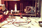
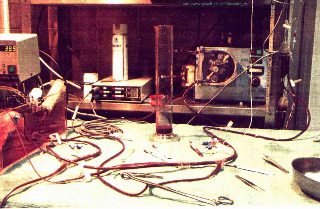
Fig.27: Il circuito durante la perfusione. In primo
piano lo shunt clampato.
Our circuit during the perfusion. The clamped bypass
is visible.
The 2 bags (15) and (16), suspended in higher position, contain physiological
solution and distilled water, used to dilute the blood and to wash the
filling circuit. The reservoir (17) can contain about 7 liters of blood,
to fill the circuit. Anyway the experiment can be carried out with less
than 3 liters of blood.
The resistance (25) is a small trimmable clamp for the tubing connected
to the placental vein. It is used to obtain the correct venous pressure:
15-20 mmHg, according to the literature [38].
Some of the mentioned elements should be described singularly. The following
paragraphs are useful for scientists who intend to realize the perfusion
circuit.
2.1.2. The
Thermostat
|
|
The thermostatic bath keeps the temperature of the solution where the placenta floats
close to 39.0°C (as the amniotic fluid) and checks
its level: a buzzer alerts the operators in case it reaches a low limit.
The pool is split in 2 sectors by a tailored
steel net in order to avoid that the placenta is damaged
by the fan of the heater.
2.1.3. The Oxygenator .
|
|
The placental consumption of oxygen is rather low: our measurements
did not give significant results as they were in the range of the
tolerance of the gas-analyser, and often not reliable,
also due to the time taken by the instrument to perform
the measurement: the values to be measured on the 2 samples change
during this time. The estimated consumption, according to
the literature [39], is 10,9 ml/min/kg.
Anyway other researchers estimated even lower values in the past
[38]:
Budelman: 3,0 ml/min/kg
Nyberg and Westin: 3,7 ml/min/kg
Goerke, Vermeulen: 3,48 ml/min/kg
Wolf: 3,6 ml/min/kg.
The oxygenator has to grant
the normal values of partial pressure of oxygen
and carbon dioxide for the blood entering into the placenta.
Our experiments evidenced that the placenta
reacts suddenly to variations of such values: presumably
this is a control system for the oxygenation, but this aspect
has not yet been analysed, we did not found any papers in the literature.
As the placenta performs the role of the lungs for the fetus, the
blood flowing into the umbilical arteries is poor in oxygen.
The oxygenator is supplied with the 3 gases O2, CO2, N2
in order to keep the venous condition for the blood.
The required values are:
PO2 = 20 mmHg
PCO2 = 40 mmHg
PN2 = 710 mmHg
The gas flows can be obtained by the ratio:
Pmixture : Pgas =
Qmixture : Qgas .
Their values are:
QO2 = 13.15 ml/min
QCO2 = 26.3 ml/min
QN2 = 461 ml/min.
The nitrogen does not react with the haemoglobin; its function is
to bring the total pressure to the atmospheric value, as
the pressure inside the oxygenator.
The oxygenator has also a reservoir and a heat exchanger.
The starting volume of blood in the reservoir is
1,5 litres. The heat exchanger allows to control
the blood temperature.
2.1.4. The Pumps
|
|
One of the two roller pums (Watson-Marlow, type MAR8) is used to supply
the heat exchanger of the oxygenator. For our convenience we used the same
fluid the placenta is floating in. The pump works at its maximum flow.
The second pump (Hospal, model DAS 262) is used for the perfusion.
It is a roller pump for dialysis working at total occlusion: time is short
and flow is not heavy, so the hemolysis due to the occlusion is fair. The
total occlusion gives a benefit: the flow is better controlled and not
depending from the pressure. The values of Table 1
have been verified up to 400 mmHg.
|
3.9
|
80
|
| 6.1 |
125 |
|
8.3
|
170
|
|
10.5
|
215
|
| 12.7 | 260 |
Tab.1: Taratura della pompa di perfusione. Velocità
misurata RPM Portata cc/min.
Verification of the flow of the pump for perfusion. RPM versus cc/min.
2.1.5. The Level Control
|
|
Already during the preliminary trials of perfusion (with physiologic solution
instead of blood) we faced the necessity of an automatic regulation of the level in the reservoir
to avoid it to get empty (pumping air into the circuit), or to reach its maximum
capacity.
As we did not found the desired instrument on the market
we developed an electronic circuit able to
restore the maximum level through a valve when it reaches a minimum value (0.4 litres),
alerting if this achievement was not possible.
The electric diagram
and the details are described in our appendices.
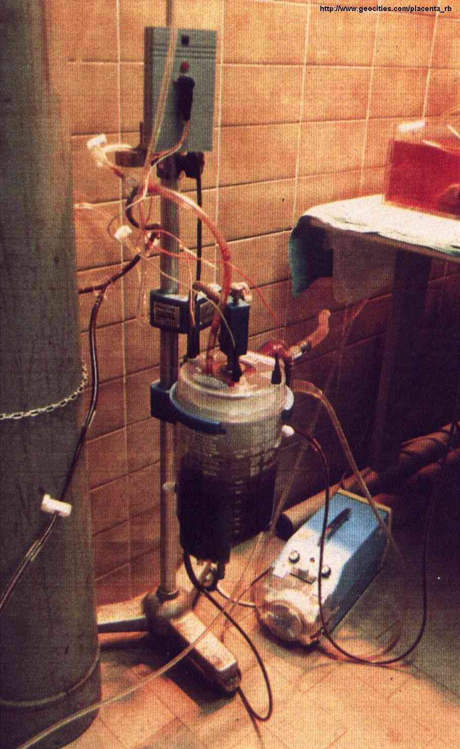
Figure 28 shows the oxygenator installed.

|
Fig.28: L'ossigenatore durante il funzionamento.
Sopra di esso: il circuito di controllo del livello, che comanda l'elettrovalvola.
In basso a destra: la pompa roller collegata allo scambiatore di calore.
An oxygenator during the perfusion.
Over it: the level control, driving a valve.
In the bottom, right: the roller pump connected to the heat exchanger.
|
2.1.6. The Pressure Meter
|
|
It is used to measure the blood pressure at the connections of the
cannelae to the rest of the perfusion circuit, with 2 extravascular transducers.
The catheters connecting the transducers to the cannulae must be short
(about 1 m) and not elastic, not to attenuate or modify the signal. Catheters
and transducers are filled with eparinated solution.
For each of the 2 channels, The Pentam meter calculates maximum, minimum
and mean pressure every 3 seconds. Two analog outputs are also available,
allowing to record the current pressure with external equipment. The gain
for the outputs can be selected: 20mV/mmHg or 200mV/mmHg.
Specifications of the meter:
- transducer supply voltage : 10 V
- bandwidth : 0-50 Hz
- resolution : 5 mmHg
- precision : ±2%
- operative temperature : 15-40°C
- full scale value : 350 mmHg
Specifications of the transducers:
- resistance : 200-600 W
- sensitivity : 50mV/V/mmHg
2.1.7. The Scope
|
|
It has been used to visualize the venous and the arterial pressure,
connected to the meter Pentam. The time-base to be used is 2 squares per
second or slower: we had to use a very old instrument to get this value.
It is also possible to use a fast recorder.
2.1.8. The Cannulae .
|
|
The cannulae used to connect the placentas are an important part of
the perfusion circuit.
Cannulae with small diameter (less than 1 mm) apparently can be inserted
more easily, but thay can damage the vessels as they are more pointed.
Moreover they cause a strong loss of pressure, consequently the pressure
cannot be measured as the meter reaches its full scale level.
Anyway bigger cannulae cannot be inserted easily into vessels whose
diameter at rest is usually less than 1 mm, but they make it possible to
measure the pressure.
The loss of pressure due to the cannulae is depending from their gauge
according to the formula of Poiseuille: 
We tried several methods of incannulation: with cannulae of various
diameters (catheter for bronchial suction Mülly made by Uno Plast
A/S, umbilical catethers 5 Ch made by Argyle-Sherwood Medical) and Venflon
needles, with the following diameters: 1.2 mm (18G), 1.4 mm (17G) and 2.0
mm (14G).
Finally the chosen solution was using two suction cannulae with diameter
2.7 mm (8F), already with rounded tips, made by Argyle-Sherwood Medical
for the arteries, and Tygon tubing with diameter 3.0 mm, with manually
rounded tip, for the vein.
Fig.29: Cannule arteriose.
Arterial cannulae.
best viewed with  res. 800 x 600.
Last updated: July 12, 2003
.