![]()
| OS Map Ref SD 801 125 |
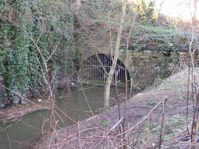
After the water had left the wheel it flowed through a tunnel beneath the mill grounds and out into the river through this archway. |
|
|
The other design feature of the waterwheel which can be seen in the drawing on the previous page, is that it uses a rim drive. From basic mechanics, power, or the rate of doing work, can be defined as force multiplied by the velocity in the direction of the force: Power = Force x Velocity If a drive shaft is only rotating slowly the velocity at its circumference is low. If it is also transmitting a high power then the forces on the shaft must be very large. These torsional (twisting) forces would tend to break the joint between the central shaft and the spokes of a waterwheel, or between the shaft and any attached gear wheel. Fractures of shafts and attached flanges were common as high power waterwheels began to be built. The solution was to take the drive from the periphery of the waterwheel using a segmented ring gear, usually of cast-iron sections, attached to the rim or spokes of the wheel. This then drove a much smaller pinion wheel which rotated at higher speed, resulting in correspondingly lower forces on its shaft. This high r.p.m. could be used more easily to drive machinery, and as a bonus the spokes of the main waterwheel could be made lighter since they no longer transmitted the rotation. The pinion wheel was usually positioned close to where power was developed, as on this drawing:
| |
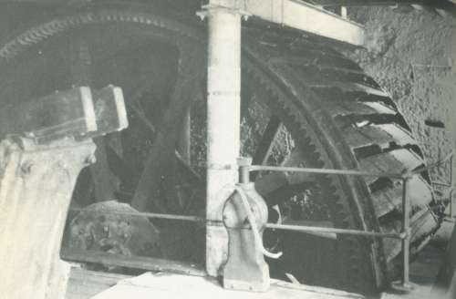
This photograph shows part of such a rim-drive waterwheel, though with an internal rather than external ring gear. |
|
|
It may seem surprising that a waterwheel was still in use in the 1850s, even though steam engines were becoming common by 1800. However there were several reasons why waterwheels continued to be built and operated well into the age of steam:
| |