The first practical steam engine was Thomas Newcomen's 'atmospheric' engine of 1712, designed for pumping water out of mines.
Working parts of a Newcomen engine, circa 1712
|
Several improvements were made to the design, many of them by James Watt between 1769 and 1787. These were:
- Condensing the steam in a separate cylinder rather than the main cylinder. This avoided wasting energy by not needing to heat and cool the cylinder on each stroke. Several designs of condenser were used, the aim in each case being to provide a partial vacuum by condensing the used steam back to water, which was then pumped out.
- Using steam pressure to push the piston down, rather than just air pressure.
- Closing the steam inlet valve before the piston had reached the bottom of its stroke obtained extra work from the steam by making it expand into the cylinder.
- Engines could be made double acting by admitting steam alternately above and below the piston, doubling the power produced by an engine at the cost of more complicated valve gear.
- A flywheel and either a sun-and-planet gear or a crank converted the up and down movement of Newcomen's engine to much more useful rotary motion.
- A parallel motion device to keep the connecting rod to the piston straight as the beam moved in an arc.
- Adapting the well-known centrifugal governor to steam engines to keep them running at a constant speed under variable loads.
|
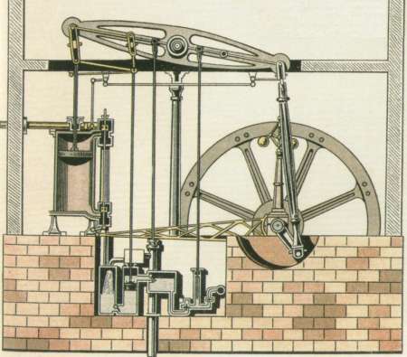
Drawing of a Watt beam engine, showing the advances described above. Early 19th century.
|
Beam engines were large and heavy relative to the power they produced and were usually mounted on stone blocks, often set into the ground. These stone blocks, with holes for mounting bolts, semicircular cutouts for the crank and the remains of pipework, may be all that remains of former engine houses.
|
The operating cycle of a single-acting Watt type beam engine is illustrated in simplified form in the animation below. Pink is hot steam from the boiler and pale blue is used steam which has done its expansion work and will be transferred to the condenser. The stages are:
- With the piston at the top of its stroke the steam inlet valve opens to admit steam above the piston.
- At the same time the part of the cylinder below the piston is opened to the condenser.
- The steam pressure from above, aided by the partial vacuum below as the used steam is condensed to water, pushes the piston down. This is the engine's power stroke.
- Before the piston reaches the bottom of its travel the steam inlet is closed. The steam already in the cylinder continues to expand and do work.
- When the piston is at the end of its stroke the connection to the condenser is closed and the part of the cylinder above the piston is connected via a pipe to that below the piston.
- As the piston moves upwards, driven by the momentum of the flywheel, steam which has done its work is transferred from above the piston to below it.
- Once the piston is back to the top of its stroke the interconnection valve closes and the cycle repeats.
Operating cycle of a single-acting Watt beam engine
|
