DDS theory and simulator
As mentioned on my interests page,
there is more theory here and also the DDS simulator for
MATLAB 5
with a graphic user interface. However, the simulator also runs
without the GUI from a MATLAB command line.
 March 4, 2004:
After about 6 years I finally got around to update the page.
I removed the commercially available chips, since
Google and other search
engines will give you what you are looking for.
There is a new thing, however. In 1993 I read the paper
by Henry T. Nicholas and Henry Samueli
[1] about the exact
calculation of the output spectrum of the DDS in the presence
of phase-accumulator truncation. Their theoretical results
and the simulation differs by about 1dB, which the original
paper contributed to the rounding in simulation. That seemed
strange, so I followed their reasoning with some variations
and recalculated the whole thing. It turned out that the
original paper neglected too much in one step which resulted
in the 1dB difference. It was a nice graduate course report
back then.
I extended the work in 1997 for another graduate course, adding
amplitude quantization to the mix. Interesting finding was
that the amplitude quantization spurs appears exactly
at the minimums of the spurs caused by the phase truncation.
I never pursued this further and then went on to do other
things in life and never went back to DDS.
I never bothered to try to publish this, so after 10 years
having the work in my drawer I finally got around to put it
on the web. It is a written from ground up specifying all
the necessary math, so it could serve as an introductory DDS material.
You can download the paper in PS format below

Theory
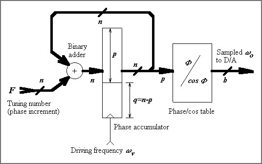
The DDS method uses a phase accumulator, driven by the specified frequency, which accumulates
the phase increments. The phase is incremented each driving frequency clock tick. The size of the
phase increment determines the actual output frequency. The binary width of the phase accumulator
(accumulator overflows) determines the minimum frequency, which is equal to the frequency
step, achievable by the DDS. The minimum frequency is defined by
 and therefore the output frequency is
 ,
where F is a tuning number and n is the accumulator width in bits. Clearly, the wider the
accumulator is the finer frequency tuning step we can get. However, to convert the phase to amplitude
we ideally have to have a converted, which would take the n accumulated phase bits as the input.
Because look-up tables are mostly used for phase-to-sinusoid amplitude conversion, with linearly increasing
n the table size increases exponentially. Therefore, for all practical purposes, the phase
accumulator has to be truncated for the phase-to-sinusoid amplitude conversion and only p
most significant bits of the accumulator are used for the conversion as shown in the figure bellow. ,
where F is a tuning number and n is the accumulator width in bits. Clearly, the wider the
accumulator is the finer frequency tuning step we can get. However, to convert the phase to amplitude
we ideally have to have a converted, which would take the n accumulated phase bits as the input.
Because look-up tables are mostly used for phase-to-sinusoid amplitude conversion, with linearly increasing
n the table size increases exponentially. Therefore, for all practical purposes, the phase
accumulator has to be truncated for the phase-to-sinusoid amplitude conversion and only p
most significant bits of the accumulator are used for the conversion as shown in the figure bellow.
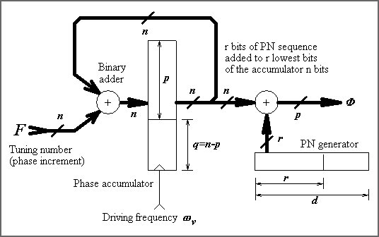
The phase accumulator truncation causes spurious spectral lines in the output spectrum.
Another source of spurious lines is the D/A converter resolution and physical
characteristics. To lower the spurious levels we can spread them over the
spectrum. The price paid is the rise of a noise floor. One of the architectures
the simulator uses is the first order dithering proposed in [6,7]. The phase dithered
DDS architecture is in the figure bellow.
Simulation of the dithered DDS architecture is a great computational
challenge. The problem is that the DDS output signal is a deterministic
periodic signal, so that should be treated as such and the theory of Fourier
series should be used. Using a pseudorandom dithering generator, we end up
with the total DDS signal period in order of megasamples and the FFT of such
a huge sequence should be calculated. It is obvious that one can run out
of resources (and patience) very quickly.
Output spectrum of the phase truncated DDS
There are several chips available on the market, which do not use any
spurious reduction technique. It is the desired to know the output spectrum
of the non-dithered DDS. The original pioneering work of DDS spectrum calculation
is in [1].
As mentioned above, here is the paper presenting the exact calculation
of the spurious spectrum of DDS as well as DDS overview I wrote 10 years
ago, taking [1] and making their results more accurate.
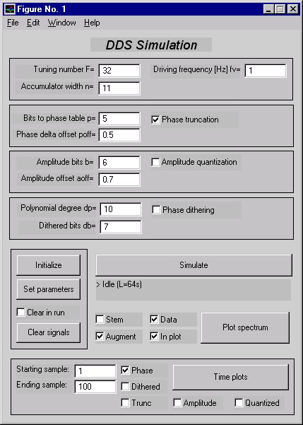
DDS simulator for MATLAB
To simulate all of these features and also to simulate some dithering techniques
for combating the spurious signals caused by the phase accumulator truncation, I developed
DDS simulator for MATLAB 5. It uses the graphic user interface now available
in MATLAB and the picture shows the DDS simulator interface in its big version.
There is also a smaller GUI with the same functionality, but smaller footprint
on the screen, which is particularly useful for screen resolutions less
than 1024x768. The comprehensive description how to use the simulator is in
the readme.txt file.
Download
Links to other DDS sites
There is a list of links to other DDS sites I collected from the Web.
More links will be coming.
References
| [1] |
Henry T. Nicholas and Henry Samueli, "An analysis of the output spectrum of direct digital
frequency synthesizers in the presence of phase-accumulator truncation,"
in Proc. 41st Annual Frequency Control Symp., Ft. Monmouth, NJ, May 1987, USERACOM, pp. 495-502.
|
| [2] |
J. Tierney, C. M. Rader, and B. Gold, "A digital frequency synthesizer,"
IEEE Trans. Audio Electroacoust., vol. AU-19, pp. 48-57, 1971.
|
| [3] |
Henry T. Nicholas, "The determination of the output spectrum of direct digital frequency synthesizers
in the presence of phase accumulator truncation," M.S. thesis, UCLA, 1985.
|
| [4] |
Paul O'Leary and Franco Maloberti, "A direct-digital synthesizer with improved spectral performance,"
IEEE Trans. Comm., vol. 39, no. 7, pp. 1046-1048, July 1991.
|
| [5] |
Jouko Vankka, "Spur reduction techniques in sine output direct digital synthesis,"
in Proc. 50st Annual Frequency Control Symp., 1996, pp. 951-959.
|
| [6] |
M. J. Flanagan and G. A. Zimmerman, "Spur-reduced digital sinusoid synthesis,"
IEEE Trans. Comm., vol. 43, no. 7, pp. 2254-2262, July 1995.
|
| [7] |
M. J. Flanagan and G. A. Zimmerman,
"Spur-reduced digital sinusoid generation using higher-order phase dithering,"
in 27th Annual Asilomar Conf. on Signals, Systems, and Computers, Nov. 1993, pp. 826-830.
|
| [8] |
Victor R. Reinhardt, "Spur reduction techniques in direct digital synthesizers," in
Proc. 47st Annual Frequency Control Symp., 1993, pp. 230-241.
|
| [9] |
G. A. Zimmerman and M. J. Flanagan, "Spur-reduced numerically-controlled oscillator
for digital receivers," in 26th Annual Asilomar Conf. on Signals, Systems,
and Computers, Dec. 1992, pp. 517-520.
|
| [10] |
Jouko Vankka, "Methods of mapping from phase to sine amplitude in direct digital
synthesis," in Proc. 50st Annual Frequency Control Symp., 1996, pp. 942-950.
|
| [11] |
Bruce Kim, Henry T. Nicholas, Henry Samueli,
"The optimization of direct digital frequency synthesizer in the presence of finite
word length effects," in Proc. 42nd Annual Frequency Control Symp.,
1988, pp. 357-363.
|
|