Projects and Tweaks TO INDEX
EMI suppressing capacitor connection and applications
Connecting of X2 EMI suppressing capacitor to
Warning! The X2 caps are to be connected across the ac line with live voltage 230Vac. 230Vac kills. Before doing any thing describes below, switch OFF the lighting and the circuit breaker. DO NOT proceed if you are unsure. I do not assume any responsibility for anything that happen to you while trying to implement the following procedures.
Lighting - Great for Suppressing the sparking of the starter.
The following figure is how the normal straight fluorescent lamp are connected. The EMI suppressing/filtering cap is to be connected in parallel to the rest of the circuit. There is no polarity with this type capacitor, metallised paper. It is all right to connect either of the leads to the Live or Neutral and the other lead to other line. The leads of caps may need to be trimmed or insulated with heat shrink.
I am using circular fluorescent lamps at home. I have made the following connection.
socket - DIY quiet line filter
There are various websites or web sources recommending putting some capacitance across the lines for filtering purpose. These sources would recommend using good quality film capacitor of 600Vdc for application. Personally, I prefer to use capacitors that are rated to be used across the line, or film capacitor will very much higher voltage rating than 600Vdc or sufficient ac voltage rating. The reason is not much on sonic aspect but more for safely.
To DIY quiet line filter, all we have to do is connect one or more film capacitors from the Live to Neutral. A resistor parallel to the capacitor may be required in order to discharge the capacitor when the RC combination is unplugged. One method is to utilized a container similar to the adapter or hand phone charger, and put all components in it.
I think the capacitor can be put within the wall socket, but this could be against the regulation, and there is not much space within the socket. DO it at you own risk.
Capacitors can also be connected between from the live or neutral to the earth for filtering, however, this also implies that there is current leaking to the earth. And when this current is excessive, the ELCB, earth leakage circuit breaker, will trip. The larger the capacitance used in this application the larger the leakage current. Use Class Y capacitor for this application.
To optimize the filtering effect of the quiet filter, I put a 0.47uF X2 cap parallel with another 0.01uF 1600Vdc/500Vac Wima FKP1 Polypropylene Film and Foil Capacitor. In this case, I can achieve a wider filtering bandwidth with what I have in hand.
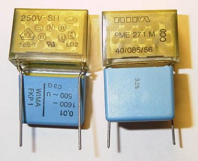
Of course these two caps can further parallel with an 4.7nF 1250Vdc/450Vac Wima FKP1 Polypropylene Film and Foil Capacitor and another or more 0.47uF X2 cap.
Due to the restriction of space for my application, I can only squeeze in a 0.47uF X2 and 0.01uF 500Vac Wima FKP1 caps. I have scattered as many of the pairs of capacitors around the power points in my flat. And I am rewarded with sound of a darker background, more detail and slightly improvement in transient. The improvement is relatively huge for the time and effect put in.
The tweaking of this CD player is based on the many published web articles on CD player modification. These articles can be found at TNT audio, Audio Asylum, DIYAudio and many other sources. Currently, most of the tweaking involve upgrading and use of better quality active and passive components, basically just components swapping. However I have implemented replacement of the 7815/7915 with LM317/LM337, JCR2930 with LM431 based shunt regulator for the DAC chips and the adaptor socket for the SIL JCR5532. I have have also constructed the Kwak Clock6, same clock circuit but different power supply with a 5ppm crystal. Based on the short listening session with it installed in the tweaked non-oscon PD-S904, the Kwak Clock gave a more analog, real and lifelike representation of music. I do not think I get improvement in soundstage, bass, detail or dynamic.
I choose this CD player as the subject of tweaking as I was using a another Pioneer CDP when I started my HiFi hobby. I missed it when upgraded to a Transport/DAC combination costing many times more of the humble Pioneer. I had some experience with the more popular Marantz 63KI and 6000OSE, I did not actually like them and they are always plagued with reliability problems, at least for my sets. In my course of searching of a cheap CDP, I came across the review of Acoustic Precision Eikos CPD at £2500, which actually the PD-S904 beef up. Of course I have the dream of making my PDS904 to sound as good as the Acoustic Precision, even without knowing how the Acoustic Precision sounds. I have now two PD-S904 with me at the moment. One heavily tweaked, and the other is a stock unit, just in case. The tweaked unit had gone through one round of modification, I had some Nichicon PL and Elna installed, but I decided to replace them with Sanyo Oscon.
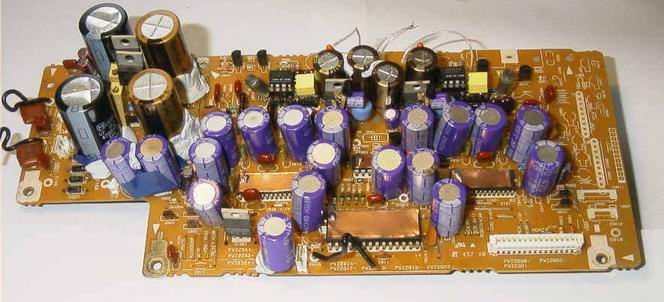
I used what I have in hand to perform the tweak. First the DAC board, it can be seen in pictures, that I have utilised many oscon caps in the power supply of the digital section, a total of 19 SA 470uF 16V and 6 SC 10uF 25V capacitors are used. These caps are further bypass with a combination of X7R 1uF 16V and 0.1uF 50V SMD ceramic cap. The ICs in the digital section are shielded with a copper foil connected to the ground.
As for the analog section, I had a hard time finding capacitors that can fit into the power supply of this section. I used two Nichicon FG 4700uF 16V cap after the voltage regulator, two Masushita 4700uF 35V cap before the regulator. The 4 caps near the opamps are the biggest headache, very tight in space, and finally I managed to squeeze in 4 silmic 100uF 50V. These caps are by-passed with some 0.47uF caps, I think they are polyester.
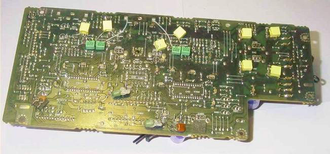
As for the transport board shown below, same thing applies. Oscon caps with bypassing of 1/0.1uF smd. 8 pieces of SA 470uF 16V caps are used here. Shield for ICs are also done. If you want the CD player to response faster, add two electrolytic capacitors to C211 & C212 on the transport board. These two caps are for IC201, pads are on the circuit board, but no capacitor install. I put in two Nichicon PL 1000uF 16V pulled from the DAC board, and the loading of CD became faster. I suppose this IC is the driver for the motors in the transport mechanism, and adding two capacitors there, its drive capability improves significantly. This is similar to increasing capacitance of an amplifier. One more thing, there are three small electrolytic capacitors on this board, two of them with the rating of 4.7uF 50V Nichicon, and the other is a light blue 0.47uF 50V. These three are used in control circuitry, not the power supply. I was itchy finger and changed them to some "better" capacitors pulled out from other parts of the CDP. After that the CDP refused to track. I had to revert back to the original caps.
![]()
![]()
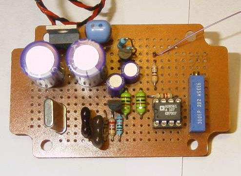
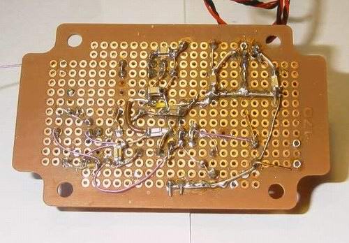
Kwak Clock as how I have implemented is shown below. For the circuit, please contact Elso Kwak, you can find him at DiyAudio. 2 SA 470uF 16V and 2 SC 10uF 25V caps are used. I had to short out the decoupling cap at the output of the clock in order for the CDP to detect the clock signal. Luckily I had another 904 with me to swap boards for debugging.
This major operation that took me 4 full days to implement and debug, planning and constriction the clock circuit not included. Anyway a short note on my impression on how the player sounded after the modification: Good overall impression, at least it is working after some unintended happenings. Very good low lever detail retrieval, I am hearing lots of more stuff from CDs that I am familiar with. Very transparent, relax, but a bit too cold and clean. Well I suppose it would need some time to run in the new parts installed.
I will posted my listening impression after I run in the machine. More detail of the tweaking will also be posted.
Future plan: Design a clock running a 4x the current frequency then divide it by 2x2. The concept is similiar to the 1388's Jon Wong clock. The 4X frequency is used for Elso Kwak's Asynchronous Reclocking. One stone two birds. Complete rebuild of the analog stage with better parts and an opamp based power supply similar to Jung Regulator.
A total 29 SA 470uF 16V and 8 SC 10uF 25V Sanyo oscon caps are used in this CD player. Of course oscon is not direct equivalent of good sound reproduction. But I am sure it is quit a sight to have so many oscon in this CD player. The electrolyte of the oscon cap is some organic compound, and thus hopefully this a the most organic CD player.
Oscon anyone?
Listening Impression and Further Tweaking of Pioneer PD-S904.
It was about two weeks since my last round of mod on this CD player. In these two week I was busy re-listening to many of my favorite CDs, I cannot stop enjoying music than to write a review of the mod. First and fore most, the coldness are all gone. The overall impression: good detail retrieval yet very smoothing and relax sounding. The sound stage improved in term of dimension and layering. The sound, or should I say sonic picture is very calm and stable. To conclude, last modification had transformed the 904 to be very musical and much much better sounding machine.
There are still areas that I was not satisfy; the high frequency performance & air. I found that the player was a bit dull for my liking. Thus I decided to see what I can do the analogue output circuit of the player.
I simulated player's filter/output circuit with protel DXP. The frequency response is as below. out11 is output of the first opamp; out1 is the output of the second opamp, thus the overall response of the filter/output circuit. I am quite shocked to see that frequency response starts to row off just after 1 kHz. On second thought, the response as such may be necessary due the the "Legato Link Conversion S" of Pioneer, which seek to re-created high frequency information that might introduce some high frequency noises. I cannot find any information or datasheet for the DAC and digital filter.
Nevertheless, I decided to try to modify the filter circuit. The response I get is such.
In my version of the filter/output circuit is able to have a flat response to 30kHz. Sonically, the high frequency performance of the player had also improved. Notice that there is a very slight bum just before the response roll off. I could make the response truly flat and roll off, I tried it out and did not like what I heard, this version gives more spark. I heard better high frequency extension and detail, the player had became slightly brighter which is what I wanted. However, I am unable to bring out the air of music reproduction. If anyone have any idea of do so, please let me know.
I did something else to the clock circuit. In the original 904, the clock signal is generated and buffered with a 74HCU04 not gate. I had upgraded the clock generation with the Kwak Clock, the buffering not gate was changed to 74VHC04 in the last upgrade. In this modification, I pulled out the 74VHC04 and connected the output of the Kwak Clock to the various outputs of the 74VHC04. The result: VERY HUGE improvement, I did not realize the benefit of the precision clock unit now. I am not too good with writing, but in short, big improvement in imaging, sound stage dimension and layering. Vocal reproduction is exceptional, for example Cai Qin Lau Ge sound so sweet, smooth and musical and with a lot feeling, or perhaps I think it should be analogue, although I do not have much experience with LP. This is the best Cai Qin Lau Ge I have ever heard in my system. With the removal of the not gate, timing seems to improves a bit.
To conclude, the result of current modification is very good; the player now is able to reproduce music with calmness, feeling, good low level detail information, stable imaging, and many other improvements. Very relax, analog and lifelike. I only have one regret; not much air the music reproduction. I have to look for ways to improve this aspect. Any suggestion?
I would like to speculate the improvements of various modifications. Oscon (SA 470uF 16V) with smd ceramic (0.1uF 50V / 1uF 16V) cap in power supply of the digital circuit. I believed that the improvement of smoothness, calmness and stability in the sound is attributed by combination. Low level detail retrieval is also one the benefits of them, I think shielding of the IC also helps a little here. I had a chance to perform components upgrade for a Sony SACD player, SCD-XE680 recently; I replaced all the electrolytic caps, Nichicon Muse FG series and FW series in the DAC section of the player with Sanyo Oscon SA 470uF 16V electrolytic capacitors parallel with 0.1uF 50 V and 1uF 16V SMD ceramic cap. I put the player back and hook it to the system, I had the same sensation as described, I would said that it more or less confirm my speculation.
Kwak Clock improves the the sound stage and imaging of the player. It also makes the vocal sounded sweeter and smoother; and the overall sound more relax, analog and lifelike. I think it also helps a little in low lever detail retrieval.
Some thoughts on precision digital clock for CD player. I did not realize how much different a not gate can make until I pulled one out of the circuit. The not gate I pulled out, 74VHC04, is one of the latest and more advanced not gate. I am rethinking or re-evaluate on clock circuit based on logic gate; clock generation/buffering, frequency halving and re-clocking.
DIY Interconnect Construction Guide
Personally, I believe that the construction/dielectric, or how the wires are arranged and the insulation materials, of the interconnect have greater effect on the sound than the material of conventional current carrying conductor. I also believe using of very thin wire for signal applications. I have gathered a few flavors of DIY interconnect receipts from the web, these designs are easy to construct. I have very good results with Chris Vanhua's recipe interconnect. Highly recommended, but troublesome to build.
Anyway, first 4 types are braided design.
The first one is a simple twisted pair of insulated conductors. This is simplest and cost effective version.
The other three versions make use to three insulated conductors. They are braided like pig tail. Using three conductors although increases the material cost a bit. On the other hand, there are three configurations that are possible from the same setup. I again believed that these configurations offer different sound.
Balanced interconnect can also be construction from these 3 wires. 1 gnd; 1 +ve and 1-ve.
A braid/shielding can be added to all four above designs. I would suggest that leave a bigger than normal gap between the conductors and the braid, perhaps some form material can be used to wrap around the conductors to increase the thickness then the slot the conductors/wrapping through the braid. Conventionally, the braid is joint to the neutral at the source end and float or not connected at the load end. There is another option: float the braid at both ends, but connect a wire to the end of the braid at the source. An crocodile clip can be connected to the other end of the wire. The clip can be clipped to the metal chassis of any components or together with other clips. This is the Aural Symphonics method. The best part of this method is that active shielding is possible; connect the +ve terminal of a 9V battery to the clip and -ve terminal to the ground of the component.
I would like to called last version the DNM Clone. I believe that this version offers the lowest capacitance. I think the diagram below is self explanatory. I do not know if there is any other sources in the web suggesting such DIY method. Please let me know if these is any.
The circuit of battery charger I have constructed can be found
http://www.uoguelph.ca/~antoon/gadgets/labc2.htm - this is Tony Van Roon's design.
I used 5A voltage regulator, LM338, instead of the LM350. The circuit is quite simple to implement and very functional. However, I was not able to limit the charging current with this circuit. Thus I searched the web for a method to limit the charge current and I managed to find a method: draining current from the adj pin of the voltage regulator; it will lower the voltage output, thus charging current will be limited. Of course there should be some kind feedback to achieve this. Extra circuit as shown below can be added to that of Tony Van Roon's.
R1b and R2b is protected the transistor 2N2222, they can be omitted. I set R1b to 100ohm and omitted R2b in my construction. R
bias is bias or turn on 2N2222, current returning from the the battery will flow through Rbias, there will be a voltage drop across this resistor, when the potential difference is large enough, for this transistor 0.6V, the transistor will be turned on, and current is drain from the adj pin, voltage output of the charger will be reduced as a result, and hence the current flowing through Rbias or the charging current is reduced or rather maintained below a certain value. This value of this resistor selected = 0.6V / current limit. This rating of resistor is Current Limit2 x resistor value, you may want to use at least 1.5x of the calculated value.This method work very well if you only use it with a permanent set of batteries or do not have to change the current limit. However, my plan is to build a charger centre. It order to have the ability to change the current limit, I built a bank of resistors and select Rbias with a rotary selector switch. It worked for higher value of resistance, but not for lower value of resistance, probably due to contact resistance of the switch or parasitic resistance in the signal path. There is another drawback, I cannot switch while the is a current flowing as the switch I used was not rated to switched DC current of the value here. A switch that can be used here will be very expensive. This method of implementation is not very elegant.
After spending months wondering what to do, I decided to construct a differential amplifier across 0.1ohm (R1 in the original circuit)
The opamp used here must be supply single capable. +Vcc of the opamp should be connected to the Vin of the voltage regulator. -Vcc to the ground. Of course the opamp must be able to accept Vin. I used a CA3140 for this application. I had tried connecting +Vcc to Vout of the voltage regulator, but it seemed that the differential amp cannot perform well when one of its input is same as the +Vcc. Connection to Vin also enables the output voltage swing of the differential amp to be larger.
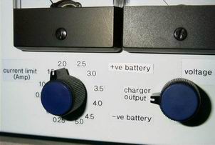
The gain of the differential amp is 24 times. Rs is actually a 12 steps switch, with different resistance connected to between the steps, thus a step attenuator. It is used control the output of differential amp to the 2N2222. I am able to have 12 settings of for the current limit. I decided to have the smallest value to be 0.25A. When this current flows through R1, the potential difference across R1 is = 0.25 x 0.1 = 0.025V. When charging current reaches this value, the transistor must be turn on, and it needs 0.6V of biasing voltage. So the gain of the differential amp = 0.6/0.025 = 24. I selected R1d = 15 kOhm and R2d = 360kOhm to give the required gain.
The next setting for current limit is 0.5A, p.d. across R1 = 0.05V, output of differentiate amp is 0.05 x 24 = 1.2V. Only 0.6V is needed to turn the 2n2222 on, so I have to attenuated the voltage by half. For current limit of 0.75A, differentiate amp's output = 0.75 x 0.1 x 24 = 1.8V, 2/3 of this voltage has to be thrown away.
I decided the value of Rs to be 50kOhm. Now I have to determine the changes in resistance for each step. Half the voltage have to be discarded if current limit is changed from 0.25 to 0.5A. The change in resistance should be half of 50kohm = 25kOhm. From limit of 0.25A to 0.75A, changes in resistance 1/3 of 50kOhm, = 16.67kOhm, this is difference in resistance from the first to third step. There is already a 25kOhm change from the first to the second step. From second to third step, the difference is 25 - 50/3 = 8.33kOhm.
The rest of the steps can be calculated as such. I complied the current limit, difference in resistance for each step and resistors used in the below table. I paralleled resistors to achieve the values I want. I used 1% metal film resistor 1/4 watt for this application. With this design, I can switch even while the charger is operating.
| Step | Current Limit (A) | Vout (V) | Volt. Ratio | Resistance | Res. Diff | Raa | Rbb |
| 1 | 0.25 | 0.6 | 1 | 50000 | |||
| 2 | 0.50 | 1.2 | 1/2 | 25000 | 25000 | 30000 | 150000 |
| 3 | 0.75 | 1.8 | 1/3 | 16666.67 | 8333.33 | 9100 | 100000 |
| 4 | 1.0 | 2.4 | 1/4 | 12500 | 4166.67 | 4300 | 130000 |
| 5 | 1.5 | 3.6 | 1/6 | 8333.33 | 4166.67 | 4300 | 130000 |
| 6 | 2.0 | 4.8 | 1/8 | 6250 | 2083.33 | 2200 | 39000 |
| 7 | 2.5 | 6.0 | 1/10 | 5000 | 1250 | 1500 | 7500 |
| 8 | 3.0 | 7.2 | 1/12 | 4166.67 | 833.33 | 910 | 10000 |
| 9 | 3.5 | 8.4 | 1/14 | 3571.43 | 595.54 | 620 | 15000 |
| 10 | 4.0 | 9.6 | 1/16 | 3125 | 446.43 | 680 | 1300 |
| 11 | 4.5 | 10.8 | 1/18 | 2777.78 | 347.22 | 430 | 1800 |
| 12 | 5.0 | 12 | 1/20 | 2500 | 277.78 | 470 | 680 |
| 25000 | 3000 | 15000 |
Res. Diff = Raa//Rbb
The resistors are connected as diagram below. When the switch is turned clockwise, its resistance decreases.
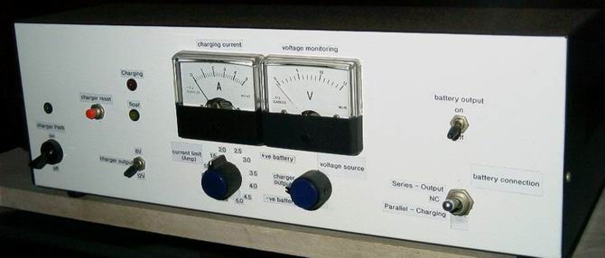
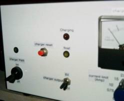
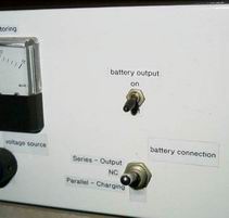
Below are some pictures of my battery charging centre. There are two 12V 7Ah SLA batteries in it. The charger can also use to charge up external battery, 6 or 12V.
|
|
||
|
|
|
|
This project to clone the Gain Card amplifier of the 47 labs. It is very popular with DIYer as it is very simple and sound quite good. More information are available in the following links and many others;
http://www.diyaudio.com - do a search.
http://www.diyaudio.com/forums/showthread.php?s=&threadid=9112&perpage=15&pagenumber=1
Building a unit is not really an issue if you can read the circuit diagram as there are many detailed information about its circuitry in the web. I would consider the challenge is the chassis, as in building a presentable one. I would not go into the circuitry as they can be found in the web. I just like to present my implementation of the GainClone.

|
The pictures on the left and below are just plan for the
implementation of my GainClone. They are on 1:1 scale, that is the actual
size of the amplifier. I decided to build it as a pair monoblock. What is
shown is actually one of the channel. Power supply will be external. The picture on the left shows arrangement the components and some simple connection. I have chosen XLR for the power supply connection, as it is relatively cheaper, the current rating of 16A for 3 pole XLR is sufficient. I will be using LM3875 power opamp IC chips as the heart of the amplifier. It will be mounted on a heat sink |
 |
This is the rear view of the amplifier. In this version it will be laying flat. I intend to built a two channels or parallel version, which will stand vertically. There might be two heatsinks mounted on the sides of the chassis. Alternatively, I could also use a thick piece of metal maybe mild steel or aluminum to replace the heat sink. |
I have almost finished with the chassis of the amplifier. I constructed them with aluminum of thickness about 1mm. After I finished them, I realised that it is a bit too thin for my liking. I am looking of a thicker aluminum to do another one. I attached some pictures of the chassis. The top and bottom plates are just aluminum plate, not very nice, I need them to hold the chassis together. And who knows I may be using them once got use to its look. And I think I will. One last thing, the rubber bands will not be there in the final construction, the pieces of chassis will be hole together by screws and bolts and nuts.
Please let me know your comments.
 |
 |
 |
 |
 |
  |