 |
| Digital Tach Page 2 |
|
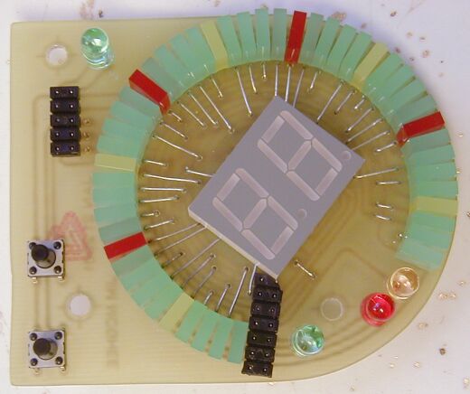
| The only visible board of the tach will be the display board. It is mounted directly behind the smoked plexiglass lens. The center two digit display will normally display the engine speed in hundreds of RPM. The digital needle of the display is constructed of 2.5x7mm rectangular LED's, each LED lights for every 100 RPM of engine speed. The yellow LED's indicate even 500 rpm increments, and the red LED's for even 1000 rpm increments. |
| The lower left push-button will select the 2 digit display mode. By default the display indicates engine rpm x100. By pressing the mode push-button, the display will sequence to read outside temperature, and with another press will display the tachometer's internal temperature. The third press of the button will sequence the display back to engine speed. The other push-button will set the display brightness in 16 steps from 0 (very dim) to 15 (full bright). Another display mode will allow the brightness to be set with the truck's instrument panel light level. |
 |
 |
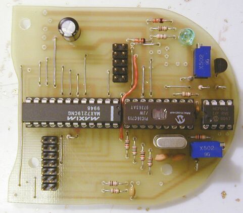
| The brains of the tachometer |
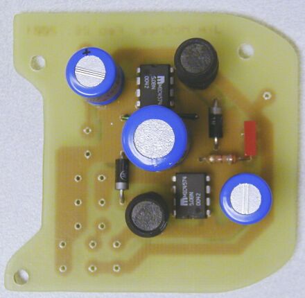
| Dual 5 volt switching regulator power supply board. |
 |
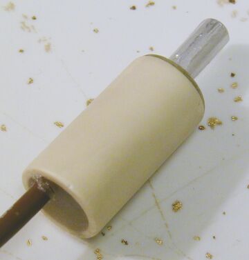 |
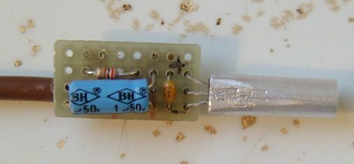
| The outside temperature sensor IC is mounted in an aluminum tube and soldered to a perfboard containing the power filter capacitors and decoupling resistor. |
| The finished outside temperature sensor is mounted in a small piece of CPVC plastic pipe and then filled with epoxy. |
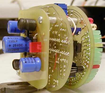 |
| Assembled tachometer circuit boards |