|
EL34 PP Amp |
EL34 PP Amp | |
| PP amp Index Power Supply High Voltage Driver tube Negative supply Heater for Driver and Output Tubes Pictures
Mail me at [email protected] |
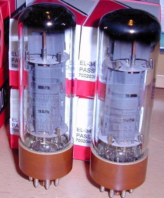 EL 34 tubes Using minimal tubes a pp amplifier can be created. Tubes that are used are 1 6922 and 2 el34. However this design needs to incorporate a preamplifier. Since there is not enough gain, no global feedback is applied. However some local feedback is applied around the output tubes to prevent inrush current from following thru went starting up. Input Stage The first stage of the amp uses a long tail pair to do phase splitting as well as provide some gain. A long tail pair is a common cathode with the signal from its cathode follows thru to the second tube's cathode. Hence this second tube is a grounded grid operated. Since the el34 were met to be in driven in triode mode, the driver tubes had to have low rp. The tubes that fit this criteria were 6922, 5842, 6c45pi and 5687. Since the tubes needs needed to have low rp and relative high mu, 6922 was chosen due to cost, mu and rp. The input stage is utilize with a constant current sink to enable almost "perfect" phase splitting. The tubes are run with 10 ma of current each to reduce their rp of their tube. Also a negative supply is used to get the plate voltage to be a negative value as well as allowing the tubes to swing more voltage on its grid. However the operation is not as ideal as calculations reveals. The 6922 plates were not 100% matched, mine was mismatch by 10%. This in turn effected the dc bias on the plate of the 6922s. The dc bias was mismatch, and hence a pot was utilize to get them to have the same dc balance. However in this setup, one could get ac balance or dc balance but not both. Since this was a single ended to differential, the voltage is divided by halve. Output swing of the first stage was only 23 db instead of the full 30 db. The dc on the plate is control by the B+ as well as B-. I set B- to be a constant and just move the B+ to get the required dc bias on the plate. The more negative on the plate sets the output tube to operate more into class A. I utilize Sovtek's 6922 but plan to upgrade it to EH6922 which is much better. Output Stage The output Stage utilizes two el34's with their grids connected directly towards the 6922 plate. The bias of the el34 is from the voltage at the tube of the 6922. At the moment I current bias the 6922's plate to be at -45 voltage. Hence running in AB but bias closer towards A. When i get more tubes I planned to bias it into A. The output stage is a mix between a fixed bias as well as cathode bias. The resistor from cathode of the 6922 to ground is there to prevent the tube from having the tube current should to the sky when the amp is turn on. This is because when the amp is turn on the grid of the el34 is at 150 volts until the 6922 is turn on then it goes to -45. Even though the EL34 takes about 15 seconds to turn on, it still draws a max current of 80 ma for a 1 second when turn on. I plan to install a thermistor in the heater of the el34 to allow for some extra turn of heating up. The output stage is currently run with el34 but can be used with most IDHPentodes/ Tetrode. Hence KT88 to 6550 can be interchange easily. However I choose EL34 as it was cheaper by more than two times the price of a KT88 of 6550 but could then source more current than the kt88 or 6550. Svetlana's were used here.
|