|
EL34 PP Amp |
Power Supply | |
|
PP Amp Index PP amp Pictures Main |
The power supply consist of various stages for driver, output , and negative supply. For the output and driver the voltage is taken of from the same set of capacitors and chokes. High Voltage B+ The B+ for the el34 is taken from R3 point and is connected to the output transformer. C2 is two huge capacitors connected in series to get the rated voltage rating. They are of Aero brand. The rest of the capacitors are BC/Philips 150uf 400v connected in series for C1 and 4 connected in series and parallel for C2. The diodes used are byv96e 1000V 1.5amps
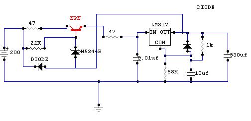
Driver Regulated B+ For the driver the B+ is taken off R3 also and fed to the below schematic via 12.5K dropping resistor. I utilize 4*50K ohm 2W carbon resistor. Total dropped across the 12.5K resistor is around 200volts. If possible utilize bigger dropping resistor 5W would be better.
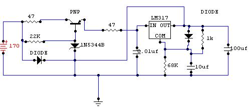
The NPN transistor should have a minimum Vceo of 400 volts. I used TIP50 with a VCEO of 450 volts. Negative Voltage B- For negative voltage the smoothing is done by the circuit below. The diodes used are byv96e 1000V 1.5amps.
The negative voltage
regulator connects to R1.
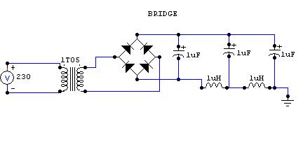
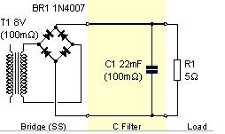
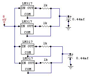
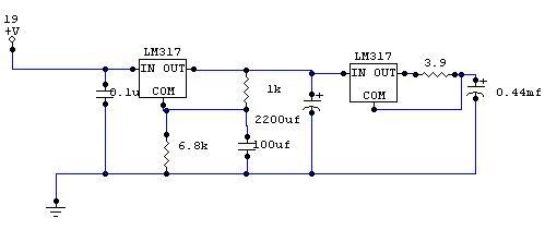
The PNP transistor should have a Vceo of 200 volts. I utilize MJE350 here but I don't recommended it. I am still looking for a device that can stand high voltage as well as high current capability than MJE350 which is a measly 0.5 Ic. I blew a couple of them while trying to get the regulator working. Note that the LM317 is LM337 as my simulator doesn't have LM337. Heater Supply The heater is supply is all DC filtered as well as being constant current for the EL34s and Constant current and Constant Voltage for the 6922 to prevent shifting of DC bias. Both of the supplies comes from a one capacitor. In the future, I am planning to add additional 22mf as well as a thermistor for slowing the heater turn on. If possible, the heater transformer voltage should be set higher around 10-11 volts so that Constant Voltage can be applied. Then everything on this amp would be regulated. Note the diodes should be able to withstand high current. I utilize a diode bridge of 35a here. Then from R1 they are connected to the heater current source below
For the driver tubes a different transformer was used. It was a 15-0-15 transformer. I used two diode and a 2.2mf cap and then connected to the below circuit. The diodes used are byv96e 1000V 1.5amps
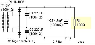
Bias voltage for the current source is a simple circuit using a voltage doubler
|