
Up
|
||||||||||||||||||||||||||||||||||||||||||||||||||||||||||||||||||||||||||||||||||||||||||||||||||||||||||||||||||||||||||||||||||||
| This page describes the construction of an Equatorial Platform for my Dobsonian telescope. | ||||||||||||||||||||||||||||||||||||||||||||||||||||||||||||||||||||||||||||||||||||||||||||||||||||||||||||||||||||||||||||||||||||
| Home Up |
||||||||||||||||||||||||||||||||||||||||||||||||||||||||||||||||||||||||||||||||||||||||||||||||||||||||||||||||||||||||||||||||||||
| INTRODUCTION | ||||||||||||||||||||||||||||||||||||||||||||||||||||||||||||||||||||||||||||||||||||||||||||||||||||||||||||||||||||||||||||||||||||
|
||||||||||||||||||||||||||||||||||||||||||||||||||||||||||||||||||||||||||||||||||||||||||||||||||||||||||||||||||||||||||||||||||||
| THE DESIGN | ||||||||||||||||||||||||||||||||||||||||||||||||||||||||||||||||||||||||||||||||||||||||||||||||||||||||||||||||||||||||||||||||||||
| CONSTRUCTION | ||||||||||||||||||||||||||||||||||||||||||||||||||||||||||||||||||||||||||||||||||||||||||||||||||||||||||||||||||||||||||||||||||||
| DRIVING THE PLATFORM | ||||||||||||||||||||||||||||||||||||||||||||||||||||||||||||||||||||||||||||||||||||||||||||||||||||||||||||||||||||||||||||||||||||
| CONCLUSIONS | ||||||||||||||||||||||||||||||||||||||||||||||||||||||||||||||||||||||||||||||||||||||||||||||||||||||||||||||||||||||||||||||||||||
| STEPPER MOTOR | ||||||||||||||||||||||||||||||||||||||||||||||||||||||||||||||||||||||||||||||||||||||||||||||||||||||||||||||||||||||||||||||||||||
| INTRODUCTION You can skip this if you know all about equatorial mounts, otherwise... | ||||||||||||||||||||||||||||||||||||||||||||||||||||||||||||||||||||||||||||||||||||||||||||||||||||||||||||||||||||||||||||||||||||
| The basic problem is that the Earth doesn't stay still for one minute, it's forever rotating (thank goodness) at a rate of approx. 15 degrees per hour about an axis centered just off the Pole Star. To track the heavens, a telescope must therefore be fixed to a mount which mimics this motion as accurately as possible. Many schemes have been designed for this, perhaps the most popular today are the yoke mount and the german equatorial mount (G.E.M.). In this computer age, the simplest method is to forget about polar alignment altogether, set the telescope up on an alt-azimuth mount and let a computer program move the horizontal and vertical axes continuously to keep track of the target as it moves across the sky. | ||||||||||||||||||||||||||||||||||||||||||||||||||||||||||||||||||||||||||||||||||||||||||||||||||||||||||||||||||||||||||||||||||||
| The Dobsonian mount is such an alt-azimuth system except that the tracking is carried out manually. Its merits are simplicity, low cost and ease of setting up. However, after some use, the astronomer gets a little tired of continually having to push the 'scope around the sky. Also, when observing under high magnification, the instrument cannot be left for more than a few seconds before the target has drifted out of the eyepiece - in two directions at once - at a surprisingly high speed !. | ||||||||||||||||||||||||||||||||||||||||||||||||||||||||||||||||||||||||||||||||||||||||||||||||||||||||||||||||||||||||||||||||||||
| If any kind of photography - film or CCD is contemplated, motorisation is a must. If the Dobsonian principle is to be retained, two systems are available - (a) fit a motor to each of the two axes and drive them from a computer, or (b) place the whole telescope and mount on a platform which is turned by a motor in sympathy with the Earth. This system is known as an Equatorial Platform. It's also known as the Poncet platform (after its designer). | ||||||||||||||||||||||||||||||||||||||||||||||||||||||||||||||||||||||||||||||||||||||||||||||||||||||||||||||||||||||||||||||||||||
| THE DESIGN | ||||||||||||||||||||||||||||||||||||||||||||||||||||||||||||||||||||||||||||||||||||||||||||||||||||||||||||||||||||||||||||||||||||
| It's best to start with a diagram (fig 1) showing the principle of operation. For a detailed description of the action however, I can do no better than direct you to this web-site by Chuck Shaw. | ||||||||||||||||||||||||||||||||||||||||||||||||||||||||||||||||||||||||||||||||||||||||||||||||||||||||||||||||||||||||||||||||||||
|
||||||||||||||||||||||||||||||||||||||||||||||||||||||||||||||||||||||||||||||||||||||||||||||||||||||||||||||||||||||||||||||||||||
| fig 1 | ||||||||||||||||||||||||||||||||||||||||||||||||||||||||||||||||||||||||||||||||||||||||||||||||||||||||||||||||||||||||||||||||||||
| Briefly, you're building a platform which rotates at the same rate as the Earth, but in the opposite direction. Furthermore, the platform can't do this just sitting on the ground, its axis of rotation has to take into account its position on the Earth i.e. the latitude of the observatory. This rotation axis has to line up with the celestial pole. Providing this is arranged, the telescope, sitting on the platform, can be swung in any direction and still track the stars (within limits - see later). The platform just keeps moving round this polar axis. | ||||||||||||||||||||||||||||||||||||||||||||||||||||||||||||||||||||||||||||||||||||||||||||||||||||||||||||||||||||||||||||||||||||
| There is a limit to this - if the platform swings too far off vertical, the telescope will fall over or the traditional Dobsonian side bearings will bind in their mounts.The simple solution is to accept this limitation and live with the idea that the platform will 'only' allow an hour or so viewing before it has to be re-set back to the start, and the telescope re-aligned on the target object. Accepting this simplifies the design no-end because the bottom bearing need only be a segment of a circle, not the whole thing. | ||||||||||||||||||||||||||||||||||||||||||||||||||||||||||||||||||||||||||||||||||||||||||||||||||||||||||||||||||||||||||||||||||||
| CONSTRUCTION | ||||||||||||||||||||||||||||||||||||||||||||||||||||||||||||||||||||||||||||||||||||||||||||||||||||||||||||||||||||||||||||||||||||
| The platform has to support, without movement or vibration, the whole weight of the Dobsonian telescope. This could be achieved by constructing it out of the same materials as the Dob. Again, the whole weight is going to be taken on bearings, so they have to be specified accordingly. | ||||||||||||||||||||||||||||||||||||||||||||||||||||||||||||||||||||||||||||||||||||||||||||||||||||||||||||||||||||||||||||||||||||
| Time for another diagram (fig 2): an outline is here, click on it for 2 more detailed and readable plans. They show all the major constructional elements. These have been updated (18.2.02) with some modified dimensions. | ||||||||||||||||||||||||||||||||||||||||||||||||||||||||||||||||||||||||||||||||||||||||||||||||||||||||||||||||||||||||||||||||||||
|
||||||||||||||||||||||||||||||||||||||||||||||||||||||||||||||||||||||||||||||||||||||||||||||||||||||||||||||||||||||||||||||||||||
| fig 2 | ||||||||||||||||||||||||||||||||||||||||||||||||||||||||||||||||||||||||||||||||||||||||||||||||||||||||||||||||||||||||||||||||||||
| Remember, the platform has to rotate about the polar axis so the first detail to note is the rear or South bearing (lower right of the plan), this points straight at the north celestial pole when the platform is level on the ground and aligned with north. The angle this axis makes with the horizontal is the same as the Latitude of the observing site. A brief 'aside' here - is the telescope's use restricted to one Latitude ? (don't know, never tried) - in theory, yes, but it can be moved to other locations within, say, 100 kilometers without seriously affecting its performance. | ||||||||||||||||||||||||||||||||||||||||||||||||||||||||||||||||||||||||||||||||||||||||||||||||||||||||||||||||||||||||||||||||||||
| The North bearing sits on the base plate, level with the horizontal, but not aligned with it. It is aligned with (i.e. at right-angles to ) to the polar axis. At my Latitude this is set to an angle of 53 degrees. This bearing supports most of the load of the telescope and mount, but the proportion of the load shared between this and the South bearing depends on the Latitude angle (at 45 deg. I assume it would be 50:50). | ||||||||||||||||||||||||||||||||||||||||||||||||||||||||||||||||||||||||||||||||||||||||||||||||||||||||||||||||||||||||||||||||||||
| The design of the platform can be calculated in a number of ways - either work it out from basic trigonometry, or draw a plan (say, 1/2 scale) on a large sheet of paper, or do the same on a computer using a CAD program of some sort - this is what I did, using CorelDraw. Whichever, the starting point is to measure the basic dimensions of your Dobsonian and find out your site's Latitude. | ||||||||||||||||||||||||||||||||||||||||||||||||||||||||||||||||||||||||||||||||||||||||||||||||||||||||||||||||||||||||||||||||||||
| Looking at the drawing (fig 2) above, I've coloured the critical dimensions purple. My starting point was to draw a scale diagram of the Dob. Next, a decision had to be made - how much space to allow under the Dob for the North bearing ? - I allowed 2 1/4 inches (57mm). That, plus the height of the Dob pillar (including its base plate) to the centre of gravity of the Dobsonian mount and telescope tube is marked on my drawing as 'H' and and is a critical dimension. Next, a line is drawn from this datum, at the angle of latitude, so that it intersects the centre-line of the Dob at the centre of gravity. The South bearing will be on this line. Just where, depends on allowing sufficient clearance for the telescope tube to be able to swing past it. Clear as mud ? take a look at the drawing again. | ||||||||||||||||||||||||||||||||||||||||||||||||||||||||||||||||||||||||||||||||||||||||||||||||||||||||||||||||||||||||||||||||||||
| A word about the centre of gravity (c.o.g.) - by rotating the assembly about this, the system will be balanced, impose the minimum load on the drive mechanism and will not be top-heavy. Just where exactly the c.o.g. is can be difficult to calculate. It is not necessarily through the centre of the tube but, I choose to take it as that, which means in practice my assembly is a little bottom-heavy but stable. | ||||||||||||||||||||||||||||||||||||||||||||||||||||||||||||||||||||||||||||||||||||||||||||||||||||||||||||||||||||||||||||||||||||
| The North bearing has to be positioned a short distance outside the width of the Dob pillar for stability. Once this choice has been made, a line is drawn from this point to intersect the latitude line at right-angles - this is line 'A' on the plan. The length of this line, to where it crosses the horizontal datum line has to be measured accurately because it is in fact the radius for the North bearing. For the same reason, the position of the bearing on the platform cannot be changed without changing that radius. The Dobsonian mount fits on the platform in the usual manner i.e. it sits on three PTFE pads and is held by a single bolt. | ||||||||||||||||||||||||||||||||||||||||||||||||||||||||||||||||||||||||||||||||||||||||||||||||||||||||||||||||||||||||||||||||||||
| If all this seems a bit obscure, don't worry, I was confused as well at this stage. | ||||||||||||||||||||||||||||||||||||||||||||||||||||||||||||||||||||||||||||||||||||||||||||||||||||||||||||||||||||||||||||||||||||
| I constructed the whole unit from 3/4 inch laminated chipboard, the first job being to cut the base board and platform. Next, the tricky bit, making the North bearing; I cut this out using a router fitted with a trammel bar adjusted to produce exactly the right radius of cut. A bevel was then cut on the board to allow it to sit at the correct angle. | ||||||||||||||||||||||||||||||||||||||||||||||||||||||||||||||||||||||||||||||||||||||||||||||||||||||||||||||||||||||||||||||||||||
|
||||||||||||||||||||||||||||||||||||||||||||||||||||||||||||||||||||||||||||||||||||||||||||||||||||||||||||||||||||||||||||||||||||
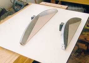
| fig 3 | ||||||||||||||||||||||||||||||||||||||||||||||||||||||||||||||||||||||||||||||||||||||||||||||||||||||||||||||||||||||||||||||||||||
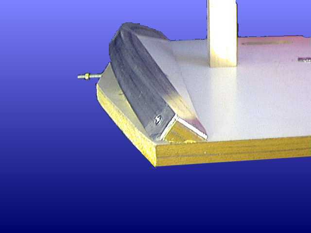
| Here's a photo (fig 3) of the bearing(s) after I had fixed aluminium strips to act a running surfaces for the ball races. Sorry ? why are there two in the photo ? see 'Conclusions' below for the answer !. The North bearing is fitted to the board by blocks in such a position that the corner of the two running surfaces lies exactly on the radius line and the bearing sits at the correct angle as shown in the pics (figs 4 & 5) here. Two other details are shown as well; a central post which contacts two limit stops on the baseboard to stop the telescope tipping too far, and, a threaded rod which engages with the motor drive. | ||||||||||||||||||||||||||||||||||||||||||||||||||||||||||||||||||||||||||||||||||||||||||||||||||||||||||||||||||||||||||||||||||||
|
|
|||||||||||||||||||||||||||||||||||||||||||||||||||||||||||||||||||||||||||||||||||||||||||||||||||||||||||||||||||||||||||||||||||
| fig 4 fig 5 | ||||||||||||||||||||||||||||||||||||||||||||||||||||||||||||||||||||||||||||||||||||||||||||||||||||||||||||||||||||||||||||||||||||
| The North bearing has to be supported - on two sets of two ball races.I used 19mm diam races with a 6mm central hole; these were fixed using bolts and plenty of washers to pieces of alloy angle, cut and filed accordingly. These were then screwed to wooden blocks. The faces on which the ball races mount have to be cut to the Latitude angle (53 deg here)and to 90 - 53 deg. | ||||||||||||||||||||||||||||||||||||||||||||||||||||||||||||||||||||||||||||||||||||||||||||||||||||||||||||||||||||||||||||||||||||
|
||||||||||||||||||||||||||||||||||||||||||||||||||||||||||||||||||||||||||||||||||||||||||||||||||||||||||||||||||||||||||||||||||||
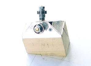
| fig 6 | ||||||||||||||||||||||||||||||||||||||||||||||||||||||||||||||||||||||||||||||||||||||||||||||||||||||||||||||||||||||||||||||||||||
| But - each block has to be inclined so that a line drawn from it would intersect the polar line and it has to be set off from square as well for the same reason (fig 6). Yes, this is tricky, both to visualise and achieve in practice. It's obvious when they're wrong, the platform won't run smoothly. To get them right, after I'd built the South bearing, I fixed each to the base board using one screw through an over-size hole. This allowed me to assemble the platform (with a weight on top) and move the top part back and forth whilst watching the bearings. When all is correctly aligned, all four ball races will stay in contact with the radius bearing throughout the full travel; the screws can then be tightened. When pushed, it will just rock nicely from side to side and come to a stop at the centre. | ||||||||||||||||||||||||||||||||||||||||||||||||||||||||||||||||||||||||||||||||||||||||||||||||||||||||||||||||||||||||||||||||||||
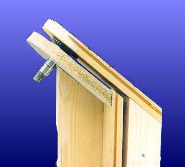
| The South bearing was made from scrap wood and firmly fixed to the boards (it carries a lot of weight). The actual bearing itself came from a defunct power drill. Having dismantled it all and removed the chuck, I found it incorporated a good sized shaft and a thrust bearing - ideal for my purpose. | ||||||||||||||||||||||||||||||||||||||||||||||||||||||||||||||||||||||||||||||||||||||||||||||||||||||||||||||||||||||||||||||||||||
|
||||||||||||||||||||||||||||||||||||||||||||||||||||||||||||||||||||||||||||||||||||||||||||||||||||||||||||||||||||||||||||||||||||
| fig 7 | ||||||||||||||||||||||||||||||||||||||||||||||||||||||||||||||||||||||||||||||||||||||||||||||||||||||||||||||||||||||||||||||||||||
| Note the angle of the bearing - correct for my Latitude. | ||||||||||||||||||||||||||||||||||||||||||||||||||||||||||||||||||||||||||||||||||||||||||||||||||||||||||||||||||||||||||||||||||||
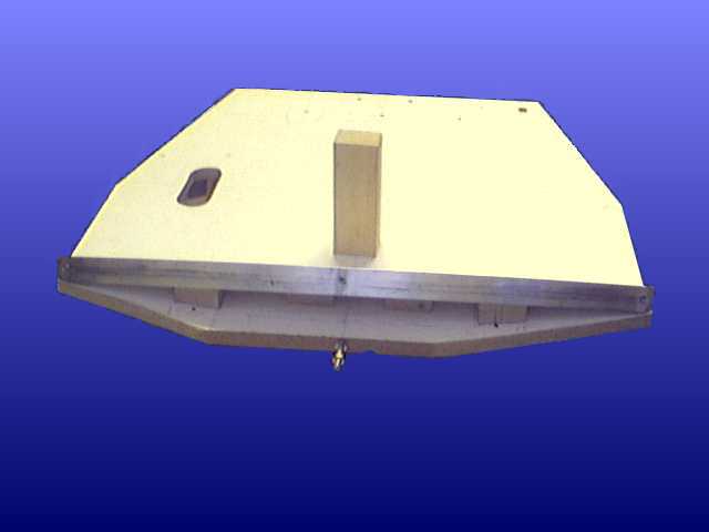
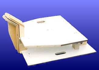
| Here's what the platform looked like with all the woodwork finished: | ||||||||||||||||||||||||||||||||||||||||||||||||||||||||||||||||||||||||||||||||||||||||||||||||||||||||||||||||||||||||||||||||||||
|
||||||||||||||||||||||||||||||||||||||||||||||||||||||||||||||||||||||||||||||||||||||||||||||||||||||||||||||||||||||||||||||||||||
| fig 8 | ||||||||||||||||||||||||||||||||||||||||||||||||||||||||||||||||||||||||||||||||||||||||||||||||||||||||||||||||||||||||||||||||||||
| Note the hand -holds; it's a heavy and awkward beast ! | ||||||||||||||||||||||||||||||||||||||||||||||||||||||||||||||||||||||||||||||||||||||||||||||||||||||||||||||||||||||||||||||||||||
| DRIVING THE PLATFORM | ||||||||||||||||||||||||||||||||||||||||||||||||||||||||||||||||||||||||||||||||||||||||||||||||||||||||||||||||||||||||||||||||||||
| First, some sums .... | ||||||||||||||||||||||||||||||||||||||||||||||||||||||||||||||||||||||||||||||||||||||||||||||||||||||||||||||||||||||||||||||||||||
| The diameter of the circle described by the North bearing is 1350 mm, hence the circumference is 4241 mm | ||||||||||||||||||||||||||||||||||||||||||||||||||||||||||||||||||||||||||||||||||||||||||||||||||||||||||||||||||||||||||||||||||||
| The platform must complete one revolution in 23 hours 57 mins i.e. 1437 mins (it can't actually do this - it would topple over !) | ||||||||||||||||||||||||||||||||||||||||||||||||||||||||||||||||||||||||||||||||||||||||||||||||||||||||||||||||||||||||||||||||||||
| So the periphery of the North bearing arc moves at 4241/1437 = 2.95 mm per minute | ||||||||||||||||||||||||||||||||||||||||||||||||||||||||||||||||||||||||||||||||||||||||||||||||||||||||||||||||||||||||||||||||||||
| There are two main ways of driving this - use a small wheel rotating on the edge of the arc, maybe substituted for one of the ball-races, or, pull the arc along using a bracket attached to a threaded rod turning at the appropriate rate. This is the tangent arm principle as used on the 'Barn Door' or 'Scotch Mount'. I opted for this method in view of my limited metal-working facilities and skills. | ||||||||||||||||||||||||||||||||||||||||||||||||||||||||||||||||||||||||||||||||||||||||||||||||||||||||||||||||||||||||||||||||||||
| The rod I obtained is M6 (5.8mm diam) with a pitch of 1.0 mm (1 turn/mm). There is a compromise here - the finer the pitch, the more smooth will be the movement and less gearing will be needed from the motor. However, fine pitch rods are normally of a small diameter and so can flex under the weight of the Dob. For a lateral movement of 2.96 mm/min, a rotation of the rod of 2.96 turns per minute is required. | ||||||||||||||||||||||||||||||||||||||||||||||||||||||||||||||||||||||||||||||||||||||||||||||||||||||||||||||||||||||||||||||||||||
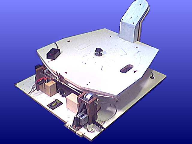
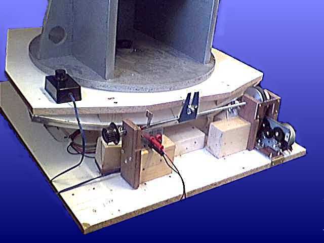
| This photo (fig 9) shows what I've built to date: | ||||||||||||||||||||||||||||||||||||||||||||||||||||||||||||||||||||||||||||||||||||||||||||||||||||||||||||||||||||||||||||||||||||
|
||||||||||||||||||||||||||||||||||||||||||||||||||||||||||||||||||||||||||||||||||||||||||||||||||||||||||||||||||||||||||||||||||||
| fig 9 | ||||||||||||||||||||||||||||||||||||||||||||||||||||||||||||||||||||||||||||||||||||||||||||||||||||||||||||||||||||||||||||||||||||
| This shows the Stepper Motor driving a pulley fixed to the threaded rod. At both ends of the rod are limit micro switch to reverse the motor at the end of the travel. In the middle of the rod can be seen the bracket which engages with the rod that sticks out from the moving table: this is secured with a nut. | ||||||||||||||||||||||||||||||||||||||||||||||||||||||||||||||||||||||||||||||||||||||||||||||||||||||||||||||||||||||||||||||||||||
| The Stepper Motor drive circuit allows for a variable speed. This is needed because the main limitation of a tangent drive is that a constant speed of rotation of the rod does not produce a constant angular movement of the driven arc (one's straight and one's part of a circle). This results in a variable tracking error which although small for small movements, needs correcting as time progresses. The hand speed controller is sitting on the platform at the left. | ||||||||||||||||||||||||||||||||||||||||||||||||||||||||||||||||||||||||||||||||||||||||||||||||||||||||||||||||||||||||||||||||||||
| CONCLUSIONS | ||||||||||||||||||||||||||||||||||||||||||||||||||||||||||||||||||||||||||||||||||||||||||||||||||||||||||||||||||||||||||||||||||||
| This was supposed to be a quick project to get the telescope motorised in a basic way before the dark nights of Autumn. It's not been quite like that !. The dark nights are here and it's still not finished. Fortunately (or not ) the skies have been terrible so - not much has been lost. The delays have been caused by problems described below... | ||||||||||||||||||||||||||||||||||||||||||||||||||||||||||||||||||||||||||||||||||||||||||||||||||||||||||||||||||||||||||||||||||||
| My first attempt at building the bearings used the modified Poncet design incorporating two arcs - a North one and a smaller radius South one. These are both shown in the photo above (fig 3). I spent a lot of fruitless hours trying to align the corresponding eight ball-races (four on each arc) but try as I may, I could never get all eight in contact with the arcs at any one time throughout all the travel of the table. That is when I changed the design to the Poncet style with one South bearing thinking this might be easier. Part way through this work I suddenly realised what I'd done wrong - I had cut and mounted the arcs at 90 - 53 degrees instead of 53 deg. ! what an idiot ! ; the ball-races were right, but the arcs were at the wrong angle -no wonder I couldn't get them to run correctly. A quick bit of work with a plane soon produced the correct angle and the North bearing was mounted back on the board. Having come this far, I decided to dispense with the South arc and continue with the Poncet style and very quickly had a free-running, correctly aligned platform - easy ! once you know how (measure twice - cut once !) as shown in (fig 9). | ||||||||||||||||||||||||||||||||||||||||||||||||||||||||||||||||||||||||||||||||||||||||||||||||||||||||||||||||||||||||||||||||||||
| STEPPER MOTOR | ||||||||||||||||||||||||||||||||||||||||||||||||||||||||||||||||||||||||||||||||||||||||||||||||||||||||||||||||||||||||||||||||||||
| The Stepper motor and gearbox combination built first was only just powerful enough to drive the platform and was therefore unreliable for real work. Increasing the gearing (more time spent) did not materially improve the situation demonstrating that the motor just didn't have enough torque for the job.The cure was either to buy a more powerful Stepper motor or try a DC motor fed from a speed controller (that was 0K but...) . | ||||||||||||||||||||||||||||||||||||||||||||||||||||||||||||||||||||||||||||||||||||||||||||||||||||||||||||||||||||||||||||||||||||
| I found on the Web a source of very cheap stepper motors and gear-boxes for �2.50. These appear to have more than sufficient torque. They were 6 - wire unipolar motors operating from 2 volts /600mA. However they seem to work very well up to 4 volts;I've subsequently fitted a 12 volt stepper motor from a 5 1/4 disc-drive - this has finer steps and allows motorised re-wind (luxury !). | ||||||||||||||||||||||||||||||||||||||||||||||||||||||||||||||||||||||||||||||||||||||||||||||||||||||||||||||||||||||||||||||||||||
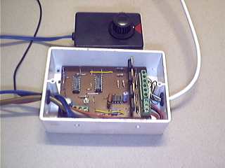
| My first controller was built from a combination of circuits gleaned from the Web. Here's a pic of the controller (fig10) with the hand-held speed adjuster behind. | ||||||||||||||||||||||||||||||||||||||||||||||||||||||||||||||||||||||||||||||||||||||||||||||||||||||||||||||||||||||||||||||||||||
|
||||||||||||||||||||||||||||||||||||||||||||||||||||||||||||||||||||||||||||||||||||||||||||||||||||||||||||||||||||||||||||||||||||
|
||||||||||||||||||||||||||||||||||||||||||||||||||||||||||||||||||||||||||||||||||||||||||||||||||||||||||||||||||||||||||||||||||||
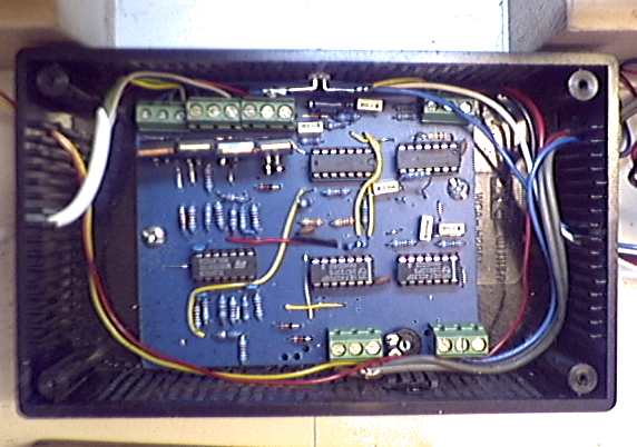
| fig 10 fig 11 | ||||||||||||||||||||||||||||||||||||||||||||||||||||||||||||||||||||||||||||||||||||||||||||||||||||||||||||||||||||||||||||||||||||
| I've now built a much better controller (fig 11) which produces much smoother, vibration - free running of the motor. This is from a design by Nils Olof Carlin, found on his web-page. My layout and more details are here. | ||||||||||||||||||||||||||||||||||||||||||||||||||||||||||||||||||||||||||||||||||||||||||||||||||||||||||||||||||||||||||||||||||||
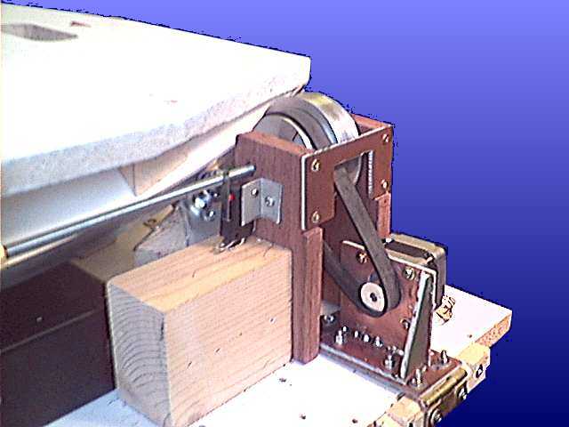
| After my previous poor attempts at gear-box building, I decided to try a belt and pulley final drive instead. A friend turned a double pulley with a 3:1 and 4:1 ratios and the belt off a vacuum-cleaner connects that with the pulley on the motor. The finished result is shown in fig. 12. Fig.13 is a general view before I changed to the 12v motor. | ||||||||||||||||||||||||||||||||||||||||||||||||||||||||||||||||||||||||||||||||||||||||||||||||||||||||||||||||||||||||||||||||||||
|
||||||||||||||||||||||||||||||||||||||||||||||||||||||||||||||||||||||||||||||||||||||||||||||||||||||||||||||||||||||||||||||||||||
|
||||||||||||||||||||||||||||||||||||||||||||||||||||||||||||||||||||||||||||||||||||||||||||||||||||||||||||||||||||||||||||||||||||
| fig 12 fig 13 | ||||||||||||||||||||||||||||||||||||||||||||||||||||||||||||||||||||||||||||||||||||||||||||||||||||||||||||||||||||||||||||||||||||
| The main threaded shaft now rides in ball-bearing races mounted in the wooden supports. The motor assembly is bolted to a hinged plate through rubber anti-vibration grommets. This allows the belt tension to be adjusted. At either end of the threaded rod are micro-switches - these are part of the automatic motor rewind system; it only takes a couple of minutes to wind itself back to the start and recommence guiding. Now, when running, the action is totally silent and accurately controlled. | ||||||||||||||||||||||||||||||||||||||||||||||||||||||||||||||||||||||||||||||||||||||||||||||||||||||||||||||||||||||||||||||||||||
| I've finally got to use the platform out under the stars - it really works !. Not shown here is a polar alignment aid I built using a monocular mounted on the platform at the correct angle of latitude and a two-way spirit level . These enable the base to be set up very quickly. The whole thing runs very smoothly, keeping on track for as long as I want to view a particular object. Compared to an unguided Dob, it's a joy to use ! | ||||||||||||||||||||||||||||||||||||||||||||||||||||||||||||||||||||||||||||||||||||||||||||||||||||||||||||||||||||||||||||||||||||