 |
|
|
|
|
|
|
|
|
|
|
|
|
|
|
|
|
|
|
|
|
|
PLATFORM STEPPER MOTOR DRIVE |
|
|
|
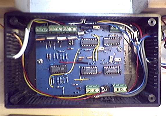
Here is the latest and smoothest stepper motor driver circuit . This was built from a design by Nils Olof Carlin and the full circuit diagram can be found on his web-page here. A full explanation of the operation will be found on that page, together with a pcb layout and waveforms by David Bevel. Note - my first motor ran off 3 volts and so Nils Olof kindly modified his circuit accordingly. My board layout and the component values below are only for this modification. The motor circuit required 3 v at ca. 600 mA , obtained via a L200 variable voltage regulator from the 12 volt supply. I've subsequently changed to a 12 volt motor and reverted to Nils Olof's unmodified circuit. |
|
|
|
 |
|
|
|
My build in its box. Note the rewind preset potentiometer at bottom and the battery state LED at the top centre. |
|
|
|
 |
|
|
 |
|
|
|
|
|
|
 |
|
|
|
Here is my pcb layout and the accompanying component placement diagram. This is a crude attempt - there are far too many wire links (shown in green) on the board !. I drew it onto the copper clad board using rub-down tranfers for the I.C. pads and a p.c.b. marker pen for the tracks. The diagrams are best saved, then scaled and viewed in a graphics program like Paintshop Pro as some of the lines are indistinct here. |
|
|
|
 |
|
|
 |
|
|
|
|