|
|
Introduction |
In This Section:Introduction to the Polygon Tools |
||||||||||||||||||||||||||||||||||||||||||||||||||||||||||||||||||||||||||||||||||||||||||||
|
| ||||||||||||||||||||||||||||||||||||||||||||||||||||||||||||||||||||||||||||||||||||||||||||||
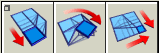
The Polygons and Polygon Edit tools are used to create, edit, and fine-tune polygonal models for real-time execution on target game consoles. Terms we usePolygonal geometry in Alias is defined in terms of vertices, edges, polygons and polysets. What is a vertex?A vertex is a point in 3D space. What is an edge?An edge is a side or edge of a polygonal model defined by two ordered vertices. A edge is graphically represented by a straight line between the two vertices that define it. What is a polygon?A polygon is an n-sided shape defined by a group of ordered vertices and the edges that are defined between pairs of those vertices. The order of the vertices determines the facing of a polygon. The polygon's front face is graphically represented using a vector described as the polygon's "normal". If a polygon's vertices are ordered clockwise when viewing a it in a modeling window, the view is of the polygon's front face. In this case, the polygon's normal is directed towards the viewer. If the vertices are ordered in a counter-clockwise direction, then the view is of the polygon's back face, in which case the polygon's normal is directed away from the viewer. >
| ||||||||||||||||||||||||||||||||||||||||||||||||||||||||||||||||||||||||||||||||||||||||||||||
|
|
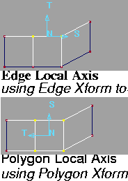
What is a local axis?Many of the polygon tools display a local axis to guide you when interactively using the tool. This local axis is formed using a polygon's normal and two basis vectors. The axis vectors are denoted with N, S, and T labels. For tools that work on polygons, the origin of the local axis is located at the centroid of the given polygon. Tools that work with edges utilize a local axis based on the polygon that the edge is part of. The axis is located at the midpoint of the edge. What is a polyset? | |||||||||||||||||||||||||||||||||||||||||||||||||||||||||||||||||||||||||||||||||||||||||||||
|
|
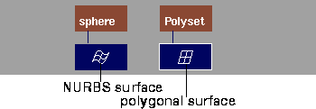
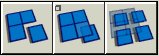
A polyset is a collection of polygonal data associated with a leaf dag node, similar to the way a NURBS surface is a collection of spline data associated with a leaf dag node. Where a NURBS surface can be described by elements such as isoparms, CVs, spans, and patches, a polyset can be described by vertices, edges and polygons. In the SBD window, polysets and NURBS are displayed as follows. Within a polyset, one or more adjacent polygons may share vertices where they meet. If one or more polygons shared a vertex, they are connected. This connectivity information is maintained when transforming or otherwise editing polygonal data. If a polygonal surface has shared vertices across most of the surface, it has smooth connectivity. | |||||||||||||||||||||||||||||||||||||||||||||||||||||||||||||||||||||||||||||||||||||||||||||
|
|
The following examples show vertices that are shared.
| |||||||||||||||||||||||||||||||||||||||||||||||||||||||||||||||||||||||||||||||||||||||||||||
|
|
||||||||||||||||||||||||||||||||||||||||||||||||||||||||||||||||||||||||||||||||||||||||||||||
|
|
||||||||||||||||||||||||||||||||||||||||||||||||||||||||||||||||||||||||||||||||||||||||||||||
|
|
Special Cases in Polygonal GeometryDeleting Hidden Polygonal GeometryHidden geometry is sometimes created when you edit and manipulate polygonal geometry. Hidden geometry is generally not very useful or desirable, especially when you want a minimal polygon count. You will most likely want to eliminate hidden geometry from your model. Hidden geometry can be found in coincident coplanar polygons. That is, it occurs when there are two or more polygons in the same polyset that share the exact same vertices or have vertices in corresponding identical locations. If this happens, there appears to be only a single polygon. This can be useful if you want to render different shaders on opposite sides of a "polygon" (two coincident, coplanar polygons with opposite normals will appear as a two sided polygon with different shaders on each side). Tips - Using the Polygon Edit Clean tools
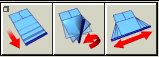
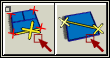
Deleting Twisted Polygons and Bow-TiesA polygon is twisted if it has more than three vertices, and those vertices do not lie in the same plane (that is, are not planar, or flat). Twisted or non-planar quads can be found using the Info > Highlight non-planar tool and can be fixed with the various Split tools. An extreme case of a twisted polygon is a bow-tie, when a polygon is so twisted that two edges of the polygon intersect. Move a vertex or vertices to untwist a bow-tie, and then use the various Split tools to produce planar geometry. Polygon Interface Summary | |||||||||||||||||||||||||||||||||||||||||||||||||||||||||||||||||||||||||||||||||||||||||||||
|
| ||||||||||||||||||||||||||||||||||||||||||||||||||||||||||||||||||||||||||||||||||||||||||||||
Polygons Palette
Polygon Edit Palette
Poly Shading Palette
Other Controls
|
| Copyright © 1998, Alias|Wavefront, a division of Silicon Graphics Limited. All rights reserved. | Please send questions or comments regarding the documentation to: [email protected] |