After mocking up the design a little and working out what sizes of steel stock I'd need, I purchased the raw materials from a local steel supplier. I got to work a few weeks ago on the cab frame...
Originally, the cab was intended to be a solid welded frame, one piece, that would have lift eyes in the roof to allow a hoist to remove it from the tractor. The problem was, once it was mocked up, I realized that my hoist was not tall enough to lift the cab high enough to clear the tires. Therefore, the cab changed course and has become a sort of hybrid between a fully welded cab and a bolt-together.
The majority of the cab frame is built from 2x2x11ga mild steel tubing. There are a few pieces of 2x2 angle iron in there too, to save weight in places where the full strength of the tubing was not required. The rear frame section . Bolts to the pads where the factory ROPS attaches, using 4 of the 8 bolts. This rear section is the back wall of the cab plus 11" horizontal legs running forward along the fenders.
The front frame leans 10 degrees from vertical to align with the angled joint between the hood and the black cowl. The front frame, like the rear, is the front wall of the cab, plus horizontal legs that run rearward alongside the platform.
Both frames have vertical sides below the top of the hood and sloped sides above it. The top of the cab frame is about 4" narrower than the bottom, mostly for looks. This was done by slicing through 3 walls of the tubing with an angle grinder, bending the tubes to fit, then rewelding the seam...
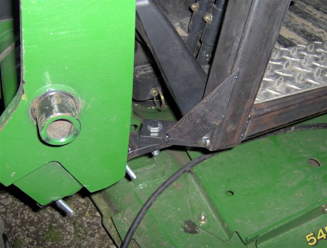
The front frame attaches to the tractor by bolting to 2 brackets. These brackets attach to the loader mounting frames using U-bolts..