Home Gallery Tutorials Downloads Other Stuff Links About Me Email
TUTORIALS
More Boolean Operations
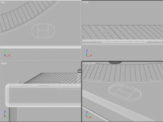
This is part two of the turntables tutorial! Sorry for the long delay, but I lost all my 3D files for this version of the turntable and so have been putting off finishing the tutorial. All pictures in this tutorial are from my 3D Studio Max version of the deck.
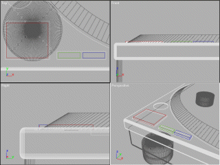
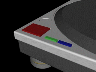
1. Part 1 of the tutorial ended with the basically completed base of the deck and turntable. Next step in the process is to add the buttons/pitch slider into the insets which we created. Firstly the start-stop button (the large one in the lower left). Simply create a cube and resize it so it sits inside the inset, with a small gap between the button and inset. Sit the lower face of the button flush with the bottom of the inset, and resize the button so it is about a unit higher than the rest of the deck. Using this same process, add in the 33/45 speed buttons. Start-stop is red, 33 is green and 45 is blue.
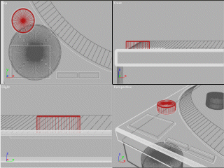
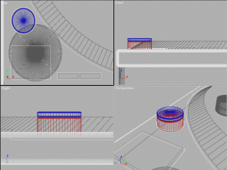
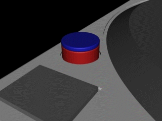
2. Next step is to create the strobe light which is used to set the correct speed of the spinning platter. To do this create a cylinder and resize it so it sits in the lower left cylindrical inset (like we did the buttons). Instead of making the cylinder about a unit higher, make it 5 or 6 units higher, so the top of the cylinder is about the same height as the top of the platter. Bevel the top edge of the cylinder by either using a bevel tool or using the same method we used to create the feet by creating a torus with the same radius as the cylinder and position it so it sits flush with the top of the cylinder, creating a seamless join from the sides of the cylinder to the torus. The bevelled cylinder is in red.
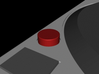
3. To complete the strobe light, create another cylinder with the same radius as the other one and sit it on top of the cylinder. Bevel/create a torus for top and bottom edges of the cylinder (use a smaller cylinder to fill in the 'hole' on the top of the new cylinder if you used the torus method). The stobe light is now complete. If you want you can also create a boolean subtraction with a cube in the side of the base of the strobe light and fit a smaller coloured transparent cylinder inside for somewhere for the light to come out of. I didn't bother doing this through as you can't see that from the angle I rendered my deck at.
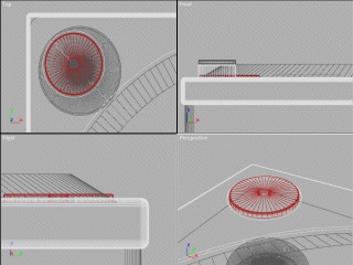
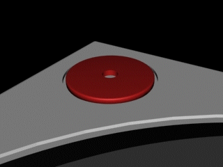
4. Use the same process we used to create the base of the strobe light for the 45 adapter, which sits in the upper left of the deck. Make the height of the cylinder 2 or 3 units higher than the deck itself. After bevelling/adding a torus to the top of the cylinder (again using a smaller cyinder to fill in the 'hole'), create a new cylinder which is slightly larger in radius than the spindle we created before and centre it in the adapter, making sure the height exceeds the height of the adapter. Now do a boolean subtraction on the adapter and it is finished.
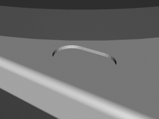
5. So far, so good. The next step is to add the light which lets you see where the needle touches the vinyl. Go to the lower right edge of the platter just near the edge of the deck. Create a cylinder of radius 1.5 (or there abouts) with the same height as the objects you created to make boolean subtractions from the deck originally. Position it so it is about 1 unit from the deck edge and the platter edge. Clone it and shift it about 3 units right. Now create a cube 3x3xthe height as the previous objects and position centrally between the two cylinders so you now have a pill sort of shape. Group all the objects just created and subtract them from the deck.
Best viewed in 1024x768 using Netscape Navigator
Copyright Michael Balzer 2002
[email protected]