|
|
The following are a few of the labs which I did in my last two years at the University of Toronto. Some labs/projects required lab reports. To see these reports in Microsoft Word, please click on the appropriate image.
Computer Organization: Project - The PathFinder
The Motorola 68000 processor system, also known as the Ultragizmo Board, is designed and developed by the University of Toronto. It has the ability to incorporate I/O devices into software programs. Some peripherals used for general weekly labs included: the keyboard, the hex keypad, the mouse, codec (microphone plugged into the PIT) and the LEGO kit.
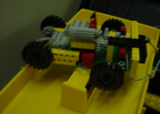
As my project, my partner and I made use of the LEGO kit to build a car which could either be controlled manually by a user using the arrow keys of the keyboard or would use light sensors to automatically follow a curvy black line (simulating a road) drawn on a large piece of bristol board.
Below is the Lego car that was built for this particular project.
Other labs using the M68000: A recursive subroutine (adding prime numbers inputted by the user), CODEC (recording a user's message and replaying it normally/faster/slower), LEGO (robotic arm which follows a light), Interrupts (adding of numbers until the user types a key and interrupts the program)
Electronic Circuits: The Optical Telephone
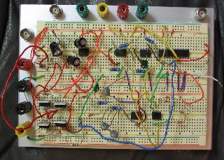
Using a small basic breadboard, some resistors, capacitors, op-amps, BJT�s, MOSFET�s, comparators and flip-flops, an optical telephone was designed and built.
The block diagram of the system consisted of:
mic -> preamp -> A/D converter -> optical coupler -> D/A converter -> power Amp -> speaker
In addition to the circuit components used on the breadboard, multiple power supplies were used to create the proper biasing for the amplifiers and the comparator and flip-flop chips. Several function generators were also used to simulate voice frequency ranges (before connecting the microphone) and to create clock signals for the A/D and D/A converters.
After many hours of debugging, each separate stage in the above block diagram worked properly on it�s own. However, there were several problems with the circuit when connected as a whole, which I was unable to fix due to time constraints. One major problem was the high noise throughout the circuit, which sometimes destroyed the useful signal needed throughout the system.
Below is my circuit at the end of the project.
|