 |
|
|
|
|
|
|
|
|
|
|
|
|
|
|
|
|
|
|
|
|
|
|
|
|
Vibrato |
|
|
|
When in reference to an LFO, vibrato is the modulation of the pitch of an audio signal in so that the frequency of that signal becomes faster and slower. The effect you will get is the pitch of the electronic instrument getting higher and then lower and then back again. The rate of this vibrato is dependent on the rate of the LFO. The higher the LFO's frequency (upwards around 20Hz) the quicker the high to low pitch rate. |
|
|
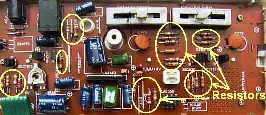
Interfacing your homemade LFO with an electronic instrument to get the vibrato effect gets a little interesting. First off make sure your instrument runs on batteries - no more than 9 volts. Next, find a Phillips screwdriver and carefully take apart the chassis of your instrument. Inside you will find all sorts of intimidating PC boards full of chips and wires and stuff. Among these things you will find resistors. The figure below shows the resistors with yellow circles around them. |
|
|
 |
|
|
|
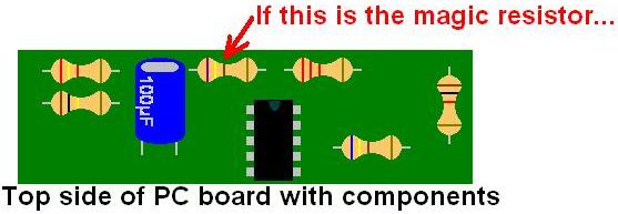
One of these resistors will make up a part of a clock oscillator circuit that keeps complicated electronic devices like your electronic musical instrument functioning (kind of like how the human heart keeps the body working). Anyway, if you change the resistance of that resistor you change the frequency at which the clock oscillator oscillates. You then "speed up" or "slow down" the operation of your electronic musical instrument. Hence you will alter the pitch of the sound. Now let's find that "magic resistor". To do this simply lick your index finger and touch each resistor while holding down a note on your instrument. When you hear the pitch of the sound get higher or lower then you found the "magic resistor". So what happened? When you touched the resistor with your finger you created a bypass for the current that was flowing through that resistor and had it flow through the saliva on your finger instead. As a result it changed the clock oscillator speed and hence changed the pitch of the sound coming from your instrument. Now all you have to do is find the two solder points of that "magic resistor" and attach the two ends of the exposed leads of the photo-resistor of your homemade vactrol to either side of that "magic resistor's" solder points. That's it! |
|
|
The drawings below depict an example of a circuit board top side and bottom side. The components (resistors, capacitors, transistors, chips, etc.) will be found on the top side whereas the solder points and traces will be found on the bottom side. |
|
|
 |
|
|
|
 |
|
|
|
 |
|
|
|
 |
|
 |
|
|
|
|
 |
|
 |
|
|
|
|
|
|
|
|
|
|
|