 |
|
|
|
|
|
|
|
|
|
|
|
|
|
|
|
|
|
|
|
|
|
|
|
|
|
|
|
|
|
|
|
|
|
|
|
|
|
|
|
|
|
|
|
Vactrols |
|
|
|
A vactrol is a combination of a photo-resistor and a LED (light emitting diode) both put into a small light-proof case. Increasing the LED brightness causes a decrease of the photo-resistor's resistance. This effect can be used in circuits that require variable resistors to obtain desired functions such as a Low Frequency Oscillator (LFO). |
|
|
Build Your Own |
|
|
As versitile as these things are, I've found that vactrols are hard to come by. Don't bother going to your favorite electronics store looking for them because they are probably not going to carry them. However you can probably find them on-line if you search long enough. Although electronics stores don't normally carry vactrols, ironically they carry the components to make your own! To build your own vactrol all you need is the following... |
|
|
 |
|
|
One light emitting diode (LED) |
|
|
|
|
|
 |
|
|
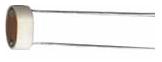
One cadmium sulfide (CdS) photo-resistor |
|
|
|
|
|
|
 |
|
|
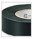
Shrink tubing or electrical tape |
|
|
|
|
|
|
 |
|
|
|
|
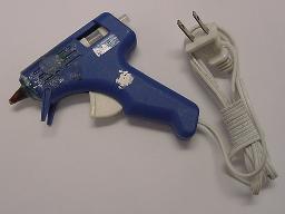
A hot glue gun (can be acquired from most art supply stores) |
|
|
|
|
|
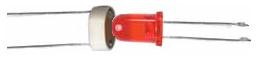
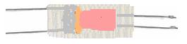
Put the LED right up against the photo-resistor as shown and put a generous dollop of hot glue on both the LED and photo-resistor. |
|
|
|
 |
|
|
|
You may want to use a helping-hands or some sort of gripping device to ensure that the LED and photo-resistor don't move about while applying the glue. Make sure the LED and photo-resistor are completely encased in glue. The good news is that hot glue dries very fast and can be "reshaped" very easily by simply holding the tip of the hot glue gun to it. Once the glue hardens you have something that looks like the following... |
|
|
 |
|
|
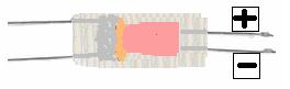
At this point it would be wise to tag the wires of the LED so that you don't forget which side is which. Use a "+" for the anode and a "-" for the cathode. I usually use Scotch tape with a Sharpie pen. |
|
|
 |
|
|
|
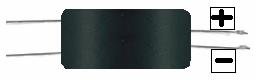
Now you need to completely cover the glued up vactrol with black electrical tape or shrink tubing. No ambient light should fall upon the photo-resistor. It must be encased in total darkness. |
|
|
 |
|
|
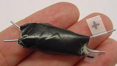
This will give you an idea of the size of one of these things. Not terribly pretty to look at but fairly compact and very versitile. |
|
|
|
 |
|
|
|
Click the Vactrol button below to take you to circuit diagrams that will interface and modulate either already bent or soon to be bent electronic musical instruments. |
|
|
|
 |
|
|
|
 |
|
|
|
 |
|
 |
|
|
|