 |
|
|
|
|
|
|
|
|
|
|
|
|
|
|
|
|
|
|
|
|
|
|
|
|
|
|
|
|
|
|
|
|
|
|
|
|
|
|
|
|
|
|
|
|
|
LFOs |
|
|
A Low Frequency Oscillator (LFO) is a circuit which generates a waveform which is used to modulate an audio signal of an electronic instrument. These waveforms can be of any form; square wave, sawtooth, sinusoidal, or triangle wave just to name a few. Usually the LFO period is adjustable from about 1 to 20 Hz. A variety of effects can be achieved using one of these things. For example, an LFO can be used to control the pitch of an audio signal (this is known as vibrato) or modulate the volume of an audio signal (this is known as tremolo). Another cool effect an LFO can be used for is stereo panning. |
|
|
|
Building Your Own Vactrol Controled LFOs |
|
|
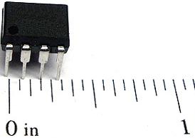
The first thing when building an LFO is to find a chip that will oscillate. My favorite is the 555 timer integrated circuit chip. It's small, pretty easy to wire up, and can be found at most electronics stores. |
|
|
|
 |
|
 |
|
|
|
|
|
|
|
|
|
|
|
|
|
|
|
|
|
|
|
|
|
|
|
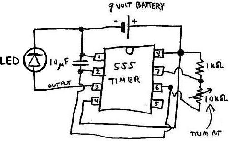
The following schematic should get you started. In addition to the 555 timer, you will need: an LED for testing the output, a 9 volt battery, one 1K ohm resistor, one 10K ohm potentiometer, one 10uF (microfarad) capacitor, soldering iron, solder, solder flux, and lots of wire (about 24 guage AWG should be fine). Again all of this can be acquired at most electronics stores. Oh yes, and grab that hot glue gun again. Although most people usually use those general-purpose component PC boards, I have actually found it easier and now I prefer to solder parts directly onto the chips themselves. It also helps to "shrink down" the overall size of the circuit. I'll then completely cover the circuit in hot glue. That way it is completely protected from the elements and the glue also serves as a strain relief for the wires that stick out. |
|
|
 |
|
|
|
|
|
|
|
|
|
|
|
|
|
|
|
|
|
|
|
|
|
|
|
|
|
|
|
|
|
|
|
|
|
|
|
|
|
|
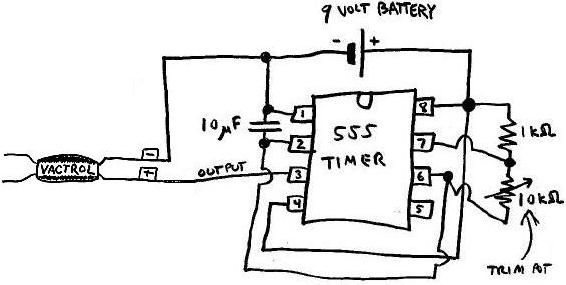
For testing the 555 circuit tie the output wire (coming from pin 3) to the anode (the "+" side of the LED) and the cathode (the "-" side of the LED) to 0VDC of the 9 volt battery. Feel free to experiment with different capacitors and resistors to get the LFO frequencies that you are looking for. As you decrease the resistance of the 10K ohm potentiometer, the frequency will increase and vice versa. Once you have a working 555 timer, remove the testing LED and replace with the vactrol. |
|
|
|
 |
|
|
|
|
|
|
|
|
|
|
|
|
|
|
|
|
|
|
|
|
|
|
|
|
 |
|
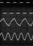
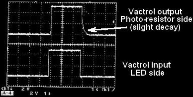
| OK, now you have an LFO ready to interface with your desired electronic musical instrument. It will be some what "squarewave-ish" with a bit of decay on the falling edge; sort of like the following. If you are planning to run your LFO at a very low frequncy - about 1 to 5 Hz and you want to have a more "sinusoidal" shaped wave, try attaching a 1000uF capcitor between pins 3 and 0VDC. Click on the links below for tremolo, vibrato or stereo panner designs. |
|
|
|
 |
|
|
|
 |
|
|
|
 |
|
 |
|
|
|
|
 |
|
|
|