|
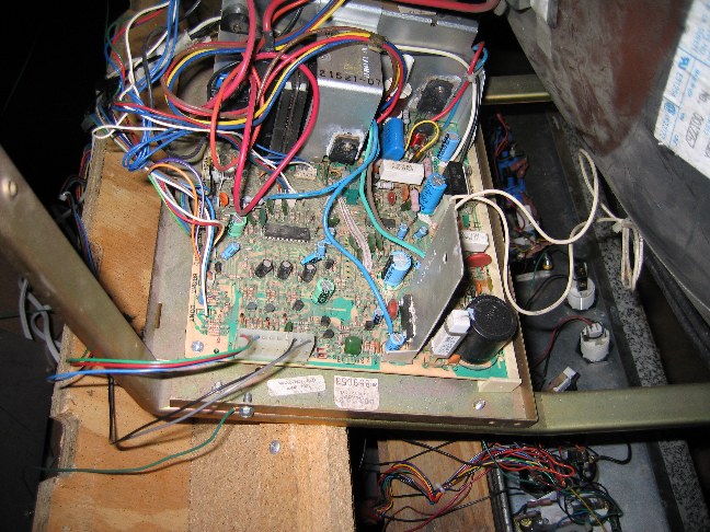
This is another photo of the PCB. You can see the back of the monitor tube at the right side of the image. Notice the white rectangular shaped resistor at the top right of the PCB, right near the big blue capacitor. This ended up being the root of my monitor problems. After about a month of researching and replacing potentially troublesome parts, I finally found the problem. The solder joint underneath the resistor had broken, probably as a result of too much voltage passing through without an isolation transformer hooked up by the previous owner. It was hard to spot, as was evidenced by my failure to get the monitor to power up after a whole month of continuous effort. I soldered the resistor back down to the board, connected power to the monitor (with the isolation transformer in between, of course) and crossed my fingers. VICTORY!!!! Finally, after this project had been in my mind for at least 2 years, I finally was able to see a game on the screen. I adjusted the v-hold and brightness a little, and it was PERFECT. Now every game (over 3,000) is just as it was in the real arcade-and I have unlimited quarters!!! |
|