|
|
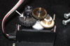
With the frame rails done, I had to get to work on hacking
the servos. The servos I chose were Hitec 225MG mighty mini metal gear ball
bearing servos. They have good torque, and (or so I thought) all metal gears
to reduce breakage. They were ~$30 from Servo
City and last but not least they weigh in at just under 1oz each. They
were really easy to hack. All I had to do was remove this pin, and take
out the pot in the back which is held in by only one screw. |
|
|
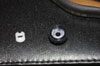
I also removed the stop that connects the pot to the output
gear shown here |
|
|
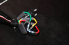
Some people glue the shaft of the pot in the center position,
I decided to use fixed resistors. Mainly because of reliability issues.
Pot's can have a tendency to drift in their readings, especially in the
heat of combat. I also think I saved a few grams, but I have no way to measure
this right now as my crappy scale reads in oz. I used the 1 percent tolerance
resistors to avoid having to use massive amounts of trim to center the servo.
|
|
|
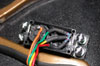
And then a neat heat shrink job and tucked the whole thing
back into the servo. |
|
|
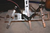
OK, so I have the drive servos, the side plates, legs bushings
and all that. Some quick lathe work turned out a couple of spacers for the
servos, and a couple of beams to connect the two sides together. Here is
one side almost completed. Very sharp eyed readers will note that the cams
you see here are not quite the same as before. I had assembled the bot for
testing and (among other things) I found out that the screw that holds the
ball links and center leg to the cam had an annoying habit of working loose.
I couldn't very well lock tite this piece in as I do need to get that joint
apart to repair anything on that side of the bot. |
|
|
I made up a pair of these thicker cams which allow the head
of the cap screw to sit flush with the back of the cam. I rebuilt the cams,
and put it back together, and suddenly, there was a horrible grating noise.
I guess I tightened one of the leg screw too much and there was some binding.
The short story is that the one plastic gear that you can see in the picture
up top, stripped itself. A frantic e-mail to hitec asking if I could get
a metal gear for this position got me nowhere. Apparently they say you have
to have one plastic gear in the train to not transfer electrical noise back
into the Rx. Well if it were my design for a servo I would have made the
plastic one the one without the tiny easy to strip teeth....hmmmm. Anyway
they did tell me that I could just use the gear set from the plastic version
of this set (which was $3.15 as opposed to the ~$12 for the metal gear set)
So I ordered 5 of em just in case. I hope this does not become a recurring
problem, but I will deal with it if it does. |
|
|
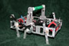
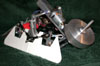
Here is a shot of the bot assembled for testing (to see if
all my designing actually works in the real world) A tad slow, well it is
a walker, but that will get better as I was only using a 4.8v Rx pack for
testing. The Rx and antenna seen here will also be gone in the final design.
The battery pack will also be replaced. I am currently trying to find out
what kind of capacity I will need/be able to get away with weigh-wise |
|
|
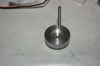
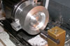
Now I turned my attention to the weapon. Here is what it starts
out as. A 3 inch diameter by 1 inch thick round of 6061 aluminum. |
|
|
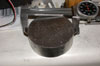
Yeah that's a big chunk. No, It's not going to stay like that. A whole
lot of that is gonna get cut away on the lathe. Here I am beginning to
cut away the waste. The weapons design is as follows. I will use a 3/4
inch box aluminum beam as the base. This will hold the motor and the base
of the rotor. (pics of this design coming soon when I figure out how to
wrench them out of autocad and get em to look good) The rotor shaft is
a piece of 1/4-20 all thread center drilled to save weight. This is threaded
through the beam and held with an aluminum retainer. The disk holds two
ball bearings. It is sandwiched between two threaded split shaft collars.
Kind of like a regular split shaft collar but the inside is threaded so
that it can be raised and lowered on the shaft to get the proper contact
with the drive wheel. Then I use the set screw to lock it in place. The
motor is held in the box beam, and a rubber drive wheel affixed to the
shaft. This gives me a reduction as well as a bit of fudge factor so that
really hard weapon hits won't be fully transferred into the motor. The
weapon disk itself will have pieces of chainsaw chain affixed like flails.
If I have time I may make several different rotors so I have interchangeable
weapon types.
|
|
|
I jump a bit ahead here, I just got a lot of work done. I will put up
explanations of how I made the other parts though, when I have time. Here
is the robot, with an almost complete weapon, and cardboard pieces which
are used to layout for the armor. Well having got that done up, I was
overjoyed to find the armor material I ordered from McMaster car, shipped
ups ground and arrived two days later from Jersey on Thursday, right after
I took that shot. Armor material is 0.125 inch UHMW plastic. I tried cutting
a piece out of a piece of scrap I had lying about and found I could dye
it with RIT fabric dye so I hope to be able to dye this stuff to make
it look cool.
|
|
|
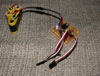
This is a regulator board that I built. I may rebuild to make
it more compact, or to use a different regulator if this one fails during
testing. The basic idea is this. The regulator gets juice from the main
battery. This is at 7.2v, which is both used to feed the regulator, and
to feed the servos. There are wire wrap pins to plug in the servos, and
servo leads to go back to the Rx. The thought now occurs to me that I could
just send the regulated voltage back through the wires that I have to plug
into the Rx for each servos control and ground wires. Anyway the Blue led
is to both "make it look cool" and provide a visual indicator
that the Rx is getting it's proper voltage. Like I say I will most likely
rebuild to make it more A) Compact B) Bulletproof C) Lighter in weight.
The idea is that I want to run the servos a bit overvolted but run the Rx
off of regulated power. The light helps to show me that the bot is "On".
That also is not the final battery pack. It just happened to be 7.2volts
and perfect for testing the circuit. For those interested that is the old
pack from Deathsycthe that never got used. I got em from All
Electronics they are good for a 350mah battery, unfortunately I had
far higher current needs than these could provide. |
|
|
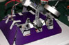
Here is the armor all cut out and dyed. I used the RIT purple
dye and basically baked the parts in the dye in the oven for a couple of
hours. Why? I like things that look cool. When I stick a couple of blue
LED's underneath this is gonna look really cool. |
|
|
I could'nt resist a test fit, everything looks pretty good,
needs a little trimming but otherwise ok. I fired up the weapon in it's
partially completed state. It scares me. Everything is well ballanced though,
and it sings when it is up to speed. Now I just have to put on the blades... |