|
|
These pages describe the design and construction of my combat robot "Morningstar".
To begin with the name comes from the whip that you get in Simons Quest
(a Castlevania game for the NES) I had got the idea in my head that whiping
things thusly with a chainsaw chain would be most fun and destructive
for robots in this weight class. I meant to accomplish this in the same
way that Deathscythe used (a friction driven spinning disc) but I had
run out of weight on DS and needed more armor, a better drive train and
a whole bunch of new stuff. So rather than upgrade and refurbish Deathscythe,
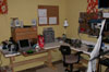
I did a complete redesign. I also had a whole bunch of new useful tools
to play with. - click on any of the pics to the left
for the larger version - You can see the new additions, from left
to right, a Delta 6" grinder, my fantastic P100 laptop stereo system,
a Taig Microlathe with milling attachment, and a 10" Ryobi drill press.
I also got a bunch of hand tools, and put the whole thing on my old computer
desk. The countertop pieces work great for that.
|
|
|
I fooled around with the design of this thing for a while,
coming up with several different ideas. I decided that it would be best
to build a walker, because I figured I could use the extra weight for bigger
batteries to put into the spinner. I threw around several ideas, and settled
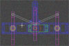
(after many revisions) on the one I had seen on Tecumseh and Reflex (to
name two). I apologize for the crappieness of those images. I'm still learning
Autocad and I'm having a hard time getting it to output what I want ('cept
for the printouts). The blue represents the base of each side, the pink
is the legs. Green is the servo and red is the cam. The grey rods connect
the cam at the pivot point of the middle leg with the outer legs. The servo
is connected directly to the cam.
|
|
|
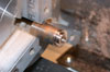
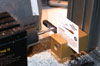
The two outside legs are supported by 1/4" axles that ride
in bronze bushings. That's what I decided to make first. This is just as
I was parting a bushing off from the rod. |
|
|
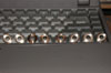
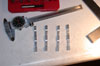
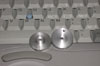
I needed 8 of these, two per leg. Here they are all done with
my laptop keyboard for scale. As mentioned before this is the "fantastic"
Pentuim 100 laptop which runs Linux and Xcdplay to supply my tunes while
building. |
|
|
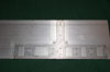
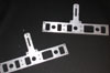
After making the bushings I turned to the legs. All legs are
made from 1/4" Aluminum, but the outside and middle legs are different.
I machined the outer legs mainly to save weight as shown here. |
|
|
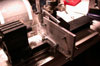
I used the Taig lathe with the milling table, but for some
reason (oh yeah lack of funds) I neglected to buy the vise for the milling
attachment. That's ok though, as the toolholder for this lathe is made to
hold 1/4" bits for the lathe and the stock I was using was 1/4". So I just
used the toolholder (squared to the bed and table of course). I might also
mention at this point that I never really have had any machine shop training
persay, shop class in school was mostly wood, so I have to learn all the
tricks as I go. So if anything I do looks really questionable (or you know
easier ways) feel free to drop me a line Send
me some mail and tell me about it. All four legs were milled and drilled/tapped |
|
|
Then I turned the 1/4" axle pieces and attached with 4-40
cap screws |
|
|
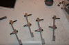
Next are the cams which operate the center leg. These were
made of 1" Al rod. These fasten directly to the servos. |
� 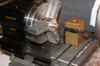 |
The second shot is of me boring the recess to go over the
servo shaft. I knew I couldn't put fancy little splines in it, but as it
turned out there was some chatter from my hommade micro-boring bar which
I belive will function as a lock washer of sorts to keep the whole thing
together. Worst comes to worst, I'll just pin it. |
|
|
Here you can see the finished cams. |
|
|
Ok, now for the hard part. The base plates. I had tried to
make up one of these earlier (I won't bore you with those pics) and it was
one huge pain in the @#$#@. You see the Taig mill table for the lathe was
never meant to mill things that are 6"x3" like the plates I was using to
cut them out of. The table has about 2" of travel in either direction. I
think I know how to get around this though, it will just require a lot of
creative thinking. To begin with I decided to mill both plates at once.
That way if there was any deviation, at least both plates would look identical,
giving it symetry at least. Look ma, I figured out how to get my inkjet
to print on aluminum!!! Just kidding, borrowing a trick from Fuzzy
I used clear window decal to trasfer the hole layout to the top plate. I
like the clear because it allowed me to line up the center marks in the
printout with the square line I scribed on the Al plate. Then I drilled
two holes through both plates and tapped them to hold the two plates in
alignment. The I center punched and drilled all the holes in the two plates
together. |
|
|
I needed to tap almost all of these anyway, and besides, at
some point I would cut out the two top screws and still need to hold the
plates in alignment. That, and I couldn't keep screws in all the holes all
the time because either the mill or the hold down bars would be in the way
of some. This way I have maximum flexibility. The round thing at the top
right is a jig I made to hold the tap square to the plates as I tapped all
the holes. I had to remove the clear decal because Al chips got under it
and pushed it up so that it was no longer correctly aligned, plus it looked
bad. |
|
|
There are the plates with a new decal put on again. I am really
pleased with this method of hole layout, Everything was as close to right
on as I could have ever hoped for. In the upper left you can see one of
the drive servos, Hitec 225MG, metal gears ball bearing, high speed, high
torque mini servo. Also the two center legs, and Revolver, which I happened
to be listening to at the time. |
|
|
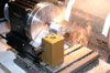
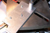
Ok. This is the tough one. I knew that it was gonna be real
hard to make these base plates on the Taig as it was. Reason being that
the table has two inches of travel in the X & Y directions. The base plate
at it's largest measures 6x3. Well, I was just gonna have to keep reclamping,
squaring and cutting. It's also hard to fit as you don't have 6" between
the center of the bit and the motor. This means at times you have to turn
the piece upside down and or backwards to get every area. Here is one of
many possible pictures from this operation. |
|
|
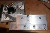
After many many hours of realigning, reclamping and milling
we end up with these. Not too shabby, and very close to identical, as they
were milled together. |