June 6, 2002
|
|
|
Ok, just a little side note. Starting
with this page I'm gonna try and date things like above so that it will
be easier to see how long things take. I make no promises as to updating
frequency however.... Anyway, on with the story of the cams. First I had
assumed I would make them out of UHMW. I had also assumed that they would
also function as the spacers between the legs to keep them from rubbing.
Well to begin with the UHMW rod wouldn't cut cleanly on the lathe. I tried
different speeds, and making sure the bit was at center height. Nothing.
It wasn't "all that bad" so I tried to drill the offset hole to
make it a cam. Ouch. Or more correctly Oomph, the sound I make when having
the pound and a half steel collet block chuck flung into my chest by the
drill press. Apparently even after drilling through first with an 1/8"
bit then a 1/4", the 3/8" bit would just bite in and spiral through,
whipping the piece and the chuck I was holding on to out of my hands. I
would have put it in the vice, but the vice does not hold the block square.
When I finally found the correct size step bit to use (another day long
story) the holes would not come out straight. I guess the OD is not all
that accurate on that rod, and hence the errors. So I decided to make em
out of Al-6061. |
|
|
Here we go with the Al. This is
the 1/2" thick blank. Due to the above fiasco I was furious at the
several days I wasted on the UHMW. I needed some 1" round 6061 and
I was impatient to get it. I would have got it from online
metals but it takes like 5-7 days and I wanted the cams yesterday. McMaster
delivered the rod in 2 days but I had to order one with a "hard anodized"
coating. They said it was at max .002" thick. How bad could it be I
thought? Kinda bad, watch out for this stuff kids. Dulls lathe bits like
crazy. But I got these blanks made up despite all the problems. |
|
|
Here is the above with the slot
milled for the spring pin to sit in and the off-center hole bored for the
shaft. I used a ball mill to get a really tight fit on the spring pin. Like
I said I had a hell of a time finding the step bit with the 3/8" step.
For some reason I was convinced that someone locally would have it (they
have all the 1/8" step models.) This was wrong. I had McMaster throw
it in with the rod. Mmmmmm Uni-bit. |
|
|
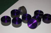
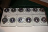
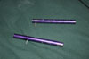
Ahhh the completed cam. Now I just
have to make the rest....uggggh more cutting through the dreaded coating.
As it turns out all of the coating is removed in creating this piece but
for various machine limitations, it needs to remain on until the final turning.
|
|
|
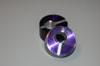
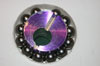
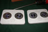
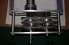
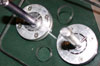
Here we see the mocked up position
of the cam. Underneath this assembly is the bearing retainer plate. Another
one will be placed on top of this but it has been removed for clarity. I
bored the hole with an 1-1/4" forstner bit. Pretty accurate in the
lexan. Everything fits well with just a little play. Surrounding it are
the 12 ball bearings that bear the load and reduce friction. Had I gotten
really crazy I could have even calculated the proper radii to make the balls
fit perfectly with no gap, but close enough is just fine for me in this
case. |
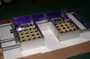 |
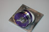
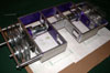
Just for kicks I decided to throw
a bunch of the HBF Sub C's in to see how many I could cram in if I need/have
the weight to. That's 32 of them in there with plenty of room (how do I
know this remark is going to haunt me later) to fit the radio gear in. I
don't plan on using this many but it's good to know I can get em in there
if I have to. I took all these apart the other night as I figured they would
be good for something, at least to use as test packs. |
June 7, 2002
|
 |
I got all the cams done today. Didn't
think I was gonna get em all done but there they are. I also rough cut the
shafts, this will not be the final length. It'll be easier to pin them with
a little extra length on them. I also finally tapped the center bar and
put it in. The first broken tap of this project. I was doing so good too.
At least it happened in the easiest piece to make, so I'm not too pissed.
Tomorrow I pin the shafts and get a start on the feet themselves. |
June 8, 2002
|
 |
Ahhh, right back to step one. But
of course I should have remembered that I wind up making half the parts
over again anyway. It seems that the bearing retainers I made in step one
were not at all accurate. I understand what I did, it was some layout technique
error. I knew it was wrong when I did it, and I did it anyway. So I got
to make 24 more, only this time the correct way. This time I used the sticker
method again. Here is the layout. |
 |
Here are half of em, the half that
need to be countersunk in fact. The other half are tapped 4-40, Yay! no
broken taps again. While I was redoing them all anyway I figured that I'd
move the holes out a little bit (they were kinda close to the bearing hole,
like 1/32-1/64). These will work much better. |
June 9, 2002
|
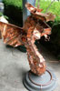 |
Not bot related but cool nonetheless.
This is a dragon sculpture I made for my parents a couple years ago for
Christmas. It's made from flexible copper pipe, 4 and 8 gauge solid copper
wire, and a load of copper foil. I had today to put the base on and reattach
the head (a cold solder joint failed) Though any readers would enjoy the
pic. |
 |
After fixing the dragon I turned
my attention to the feet. Here are two. I had cut out three, but there were
some inaccuracies in the bearing hole drilling in the third one. It's a
little tricky to do, I used a forstner bit which is made for wood but works
in the plastic. You have to go real slow, and keep backing out the bit.
It gets really hot, and tends to melt a thin layer back onto the inside
of the hole, thus necessitating the need for long painful scraping with
an x-acto blade and some sandpaper. You can just make out the remainder
of the 3/8" shaft that I stuck a pin in and chucked in the drill. I
used this to "run in" the bearings. Pretty smooth now, might need
a bit more work later. |
 |
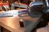
A totally gratuitous shot, mainly
to illustrate how the invertability works. The feet simply stick out of
both the top and the bottom of the bot. The top and bottom will be covered
with 1/8" lexan both as armor and to keep the electronics in. The shafts
still need to be pinned and I need to make the other 4 feet. |
June 13, 2002
|
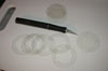 |
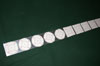
One thing I can say to anyone thinking
of attempting a design similar to this one; think twice. This is one of
the most frustrating things I have ever attempted. This shot is of a bunch
of shims I had cut out of transparency material. Basically the ball size
is the same as the thickness of the lexan feet. When you put on the retaining
plates they squeeze the balls too tightly, and don't allow them to move
freely as they should. I printed the design onto sheets of transparency
material and cut em out with an x-acto knife. Now the bearings spin very
nicely. |
 |
At long last all six feet completed.
I had originally planned to cut them using a router trim bit and a machined
template. This did not work, the bit kept kicking back and gouging, it was
a huge mess. Instead I used a painstaking process that goes something like
this. Cut out to rough size with a jigsaw. Rough sand to 1/16" with
a drum sander, then use progressively finer grits in a palm sander to get
the edges smooth and straight. Overall I am quite satisfied with the results.
Just for fun here are some numbers.....6 feet, 12 cams, 24 bearing retainers,
60 shims, 48 4-40 flat head socket cap screws, and 144 1/4" bearing
balls. Everything except for the bearing balls and cap screw was all custom
made. That was a lot of work |
 |
At last, assembly of the legs. I
didn't get a shot of the drilling to pin the shaft, but I will tomorrow
when I complete the other side of the drivetrain. This is where the frustration
really came into play. Basically it goes like this. Take the pinned shafts
put a pin in the innermost hole of each one, then put the legs onto the
shaft with the slot in the cam facing the pins. A little tapping with the
hammer to seat the spring pins in the slot. Then cut a very narrow (a little
less than 1/8") section of 1/2" OD Al tube, and put it over the
leg to serve as a spacer. A little tapping to seat that and then another
set of pins. Repeat two more times, with much screaming and cursing as the
pieces did not want to listen. They eventually did as you can see in the
shot. I also cut the chain and installed it. Dunno if I'm even gonna need
tensioners as the chain fits pretty close without them. |
 |
Now for the moment of truth, I grabbed the spare battery I had for Morningstar
and a couple of wires, and put the whole thing on the living room floor.
YES!!!!!!! IT WORKS!!!! Words cannot express my jubilation at the fact
that this thing actually works. It's not super speedy but it moves pretty
well for a walker. I was also only testing on 6 cells. I'll probably run
with 7 or 8 in the end depending on how I decide to control this thing.
|
June 14, 2002.....IT WALKS
|
 |
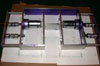
This is the setup I used to cross
drill the shaft "accurately". To have three feet on a side, each
one should have a 120 degree offset from the last. How do I do this? With
this collet block chuck. It uses a huge (if you are used to the dremel collets
this is huge) 5C collet. You put the work in the collet and tighten it down
with a nut on the back. The fence that I clamped down keeps the bit in the
center of the shaft. You simply set up the block, then drill the first hole.
Since it's a perfect hexagon you rotate two sides (each side of a hexagon
is 60 degrees) and presto perfect 120 degree spacing. |
 |
These are the two shafts with the
first set of pins installed. The second side of the drive went together
with much less cursing so I was able to calm down and take some shots as
it went together. |
 |
The first leg is installed, followed
by the spacer (you can barely make it out under the pin. Then another pair
of pins is installed. Then you just repeat the process for the other two
legs. A final set of spacers is then added to the ends to fill the gap between
the last leg and the frame. This prevents the bushings from coming out. |
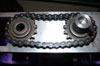 |
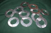
The completed chain and sprocket.
I got really really lucky and didn't really have to futz with the chain
a whole lot. It seems that I chose the almost perfect spacing for the sprockets
so that it was reasonably tight without a tensioner. You can see the coupler
on the right. I know that before I said I would pin the coupler to both
shafts but this turns out to be really impractical. Besides which there
is not too much torque transmitted there. This sounds counterintuitive but
it's true. Last night I had run one side without any fastening whatsoever.
It's because the legs themselves transmit torque between the shafts as do
the chain and the flats on the shafts. I added these setscrews more as insurance
against sideways motion. This also avoids the nightmare of having to line
all this stuff up as I try to install the pins in the tiny half inch wide
space. |
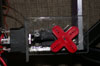 |
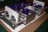
Time for some ghetto wiring. This
is a "speed control" Very simple, cheap and fast. They will not
be the final control option for this bot. All it is is a Radio Shack 20
amp automotive DPDT momentary switch and a Hitec HS-303. I made some quick
lexan brackets to hold the switch and servo in the proper relation to each
other, and slapped on this big servo horn which happened to be perfectly
suited for this job. I didn't even have to hack at it with an x-acto! Best
part of these things is I didn't have to measure or mill anything. I bent
the lexan with a propane torch. A little simple wiring and I was set to
go. |
 |
Here it is in all it's
glory. You can see my ghetto speed controls are way too big to fit inside
the frame but they live happily on top for the time being. This thing makes
a huge amount of noise stomping around. If you have some annoying downstairs
neighbors give me a yell :) It's not super fast but it does move pretty
well. I think that ESC's will actually make it move faster. Reason being
that moving the legs slower may actually work better and stop the jumping
around that goes on when you move the legs so fast. |
 |
A final gratuitous shot of the day's
efforts. You can also see the treads on the feet in this shot. They are
vacuum cleaner belts that I split in half. I am very pleased with the way
this has turned out. I made my own deadline of getting it to walk by the
end of this week. There is much more work to do to complete this bot, attaching
the armor, and building the weapon. Of course I need to finalize the electronics
as well, it would be hard to make the bot invertable with those huge switches
on the top. |
June 23, 2002
|
 |
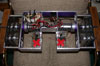
Didn't get all that much done this
week after last weeks building frenzy. The good news is that almost all
the parts are on the way for the weapon (I still need one more McMaster
order), as well as the real electronics. In this shot you can see the bottom
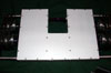
(or it could be the top as it's invertable) lexan plate bolted on. Just
like in cheap office furniture the thin plate fastened onto all the frame
members will add a whole lot of strength to the frame. It also provides
a convenient retainer for the batteries and electrics. I trimmed it to just
the right size with a router and ball bearing trim bit. |
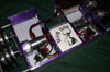 |
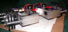
Still not yet at the final electronics
set up but getting closer. The servos will be gone in favor of a couple
of RCE's from Team Delta more on them when
they arrive. I bolted on the top plate on and if you look really close you
can see there are a couple of miss-drilled holes. Since I have to make it
again anyway I ripped off the covers so I can see what's inside and plan
any of the holes I'll need for the safety interlocks and possibly a fan
or two if I have room (not likely at this point). I also picked up some
cool purple 12 gauge wire from the local auto-sound store. $.60 a foot for
two conductors, not too shabby. Best thing, it's massive and it fits in
with the color scheme. If I get really crazy I may try and find some of
that 12v glow wire and put that in there. I threw in the Team Nar logo as
well, hiding underneath is the Rx, the soon to be reworked regulator board
and the power distribution strip. |