| |
Hello and welcome to the first build page for my new robot Belladonna.
For those who don't know, Belladonna is the Latin name of a flower, or
more actually a flower family. It means nightshade or in this case Atropa
Belladonna which means deadly nightshade. According to Kirstin's herb
book it is a "toxic leaf that causes palpitations, hallucinations,
delirium, and death.". Perfect name for my new robot. I have decided
not to spill the beans just yet on the entire design as I think that would
be spoiling the surprise. After HSRC02 I decided to build a 12lber, however
I was unsure of the design. At the time I thought to make a larger version
of Morningstar but
decided against it, because as I see it there are different challenges
in the 12lb class. I played with the idea of a wheeled drive, but I seem
to be hooked on the idea of walkers. The design I had for a wheeled bot
was cool, but it was too close in the weight department for my liking,
and required that I spend a lot of cash on cool lightweight parts. Opting
instead for a walking design gave me more to play with, so I should do
more of what I wanted. The full design will be revealed in the course
of this build report, so stay tuned for more...
|
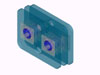 |
In any case the pic to the left details the design
for the leg mechanism. It's a bit confusing to look at cause there are a
lot of parts. It breaks down like this : Legs themselves are .25" lexan
sheet. Cams are UHMW and grooved to accept bearing balls. These bearing
balls are hardened .25" balls which are held in place with two retainer
plates which sandwich the lexan. The hole in the retaining plates is large
enough to prevent the cams from jamming against them, but small enough to
keep the balls from slipping sideways. Cams are keyed to the shaft, and
sprockets link the shafts together as well as to the drive motor (this is
not shown in this diagram). As near as I can figure it, the most important
part of such a design is to reduce its friction, and in a mechanism like
this it is easy to cause. Simple misalignment of the cams with each other
will cause binding and power robbing friction as well as having the sides
of the leg touch each other. The chain drive and keyed shaft ensure that
these stay in alignment. The captured balls provide both relief from friction
of the cams against the holes as well as friction caused by side loads against
the leg (i.e. a wedge pushing from the side). The cams are not too far offset
either, so that the step length is rather short. I figure that quicker smaller
steps is a good thing as torque is basically determined by the length of
the lever (the cam). I can get away with a lower torque motor if I use smaller
cams. |
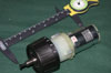 |
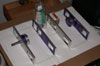
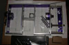
Here is one of the HBF drill motors I plan on using. It's
a 9.6v version with the plastic first set of gears. I bought two to see
if they were any good. I think I'm gonna buy a bunch more so I can swap
to get all steel. Hell, at $10 apiece (and you get a crappy battery to boot,
at least good for some testing battery packs...) I really can't afford not
to. Worst comes to worst I wind up adding 4WD to my office chair with them
if they are no good for this project. About the only thing I don't like
about 'em is the motor itself. It looks really cheap (as one would expect
with a $10 drill). If there is a problem with them, I would anticipate the
brushes blowing apart from the look of 'em, I will replace them with a couple
of 550 sized RC car motors, most likely modified ones. |
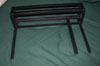 |
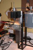
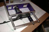
Here is the nifty frame that Kirstin's father helped me weld
up. Big thanks to Mr. Acton. It's to hold the Taig lathe. It also lets me
turn the whole thing upright so that when I use the milling attachment I
don't have to crane my neck over to be able to see what I'm doing. It also
moves the top of the motor lower than the top of the cross slide which lets
me mill longer pieces more easily. |
 |
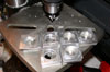
I started out the actual construction with these, the retainers
for the bearings in the legs. There are two at each bearing location. They
hold the bearing balls inside the .25" lexan leg pieces. I needed to
bore the center to a fairly precise 1" hole. Not having a boring head
or a 1" bit I devised this system hold the pieces in a lexan disc and
bore out the inside. Works great. I had to tap four holes in each as well
as mill em all square. |
 |
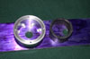
That looks great, now I just have to make these 23 more. 4
for each foot, 6 feet. Amazing, I tapped 96 4-40 holes in a row with the
same tap, didn't break a single one. I must be getting better at this. |
 |
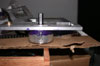
Here is the Taig in the milling position. I just drilled a
1/4" hole into the bench and used a couple of huge washers (well actually
one of the old Deathscythe disks) with a bolt to secure it in the upright
position. Now I can use it like an actual mill. |
 |
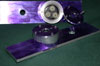
To begin the gearbox construction I started with these support
beams. They hold the motor/gearbox on one side, and on the other runs the
coupling chain and the legs themselves. You can just make out the new Uni-bit
that I got and used to cut the 1/2" holes for the bushings. There needs
to be a little more work done to make the bushings fit right, but I'll explain
that later when I get to doing it. |
 |
You might have been wondering what the set of 8 holes was
for in the above pic. They are for this, the ring gear from the HBF drill
gearboxes. You can see the set of 8 "teeth" that protrude from
the bottom of the ring. They are used in the drills gearbox as part of the
clutch system. I don't want or need that, so these holes engage the "teeth"
preventing the gear from rotating. The 1/4" wall thickness tube substitutes
for the nylon case that comes with the drill. Probably overkill in the strength
department, but who cares. The tube is just tall enough so that with the
cover on, it holds the ring gear securely into the holes. |
 |
Here we see the completed pair of gearbox/support frames.
I put in the planet gears and holder in the upright one so you can see what
it will look like once I modify the output shaft, and get the bushings installed.
The lower has the gearbox cover/motor holder in place. |
 |
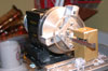
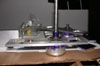
Here is kind of an overview of the bot so far. I turned down one of the
shafts for the drill gearbox to fit the bushings (and to fit the sprocket).
I also trimmed the flange on the bushings a bit. This was because the
Uni-bit I bought would only make the next sized hole 1/16" larger,
and the flange was 11/16" while the OD of the bushing was 1/2".
That meant the the bushing hole needed to be two and a half steps larger,
which would mess up the fit on the OD. With the bushing turned down and
using only one extra step to hold the flange everything fit great. Then
I milled up the two inner rails. I printed out a couple of sheets of the
design from Autocad and taped em up to some cardboard to get a better
idea of the actual layout. I still have to countersink the gearbox and
motor holes. Clearance is going to be a big issue on this bot, as everything
is pretty much crammed in from side to side.
|
 |
Here is the further modified output shaft for the HBF drill
gearbox. I shortened it and milled this flat down the length of it. I also
countersunk the gearbox holding screws to clear the sprockets and chain.
|
 |
This shot shows the sprocket on the shaft, then the coupler,
and finally a mock up shaft. The coupler will be pinned to each shaft. The
reason I needed to do things this way is complicated and basically boils
down to the machining limitations of my small tools. It also has to do with
the limited amount of room in the gearbox. I would have just pinned the
spider from the last set of planets to the shaft but I don't have the room
inside the gearbox or thickness of the spider to make this work correctly.
Ahh well. |
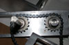 |
Here is an above shot. The sprockets transfer power between
the two shafts and lock them to each other. It may be overkill but I can
always remove them if they are not needed later. The second shaft also has
a flat on it to accept it's sprocket. I am not so used to machining steel
(all the other bots were Al or plastics with only very small steel parts)
I got a good education today in some of it though. There will of course
be some small UHMW chain tensioners applied here later to keep everything
in line. |
 |
The frame is beginning to come together. After a bunch of
wrestling with trying to create the cams (more on that in a bit) I gave
up on that project and began to finalize the frame construction. Here you
can see almost all the frame completed. I still have to put on the second
leg retaining bar and attach the center piece. A couple of parts still need
to be pocketed as well. I figure that when I go into a panic about having
to lose weight later I can do it then. All the junk on the right side is
to prop up the retaining bar. In this shot I haven't drilled the holes to
hold it to the chassis yet. If you look really close you can see some Al
cams that are not what I wanted to make. It's a long story. |
 |
I got the motors all mounted up. I think they are going to
require some sort of spacer plate. That'll wait for now as I have more important
fish to fry. There are three partially finished cams on the indirect axle.
All these need is the groove for the bearing balls to ride in. |