June 30, 2002
|
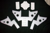 |
Well, as of the last report I had the drivetrain and frame almost complete,
so now it's time to work on the weapon. I designed it to be almost a separate
attachment, although it is integral to the design of the bot so it most
likely won't be interchangeable (you never know though, it just might
be). In any case here is the beginning of the weapon, all cut from 3/8"
thick UHMW plastic. This stuff is really tough, and for my limited tool
set, difficult to cut accurately. Most was rough cut with the jigsaw and
then sanded to final size with the drill press drum sander. It does not
like sanding too much, specially concave surfaces where more than a little
of the drum's surface contacts the work. The small interior corners and
notches were cut with an x-acto and a lot of patience. I had to break
out a whole lot of old woodcarving tricks to get it right. The result
is close enough, as most of this assembly doesn't have to be really super
precise.
|
 |
These are the 1/2" square braces that hold the above
pieces together. You can see in the above pic the rows of holes in the larger
pieces. All are drilled and tapped 10-32 for some more socket head cap screws.
There are a couple more Al braces that need to be cut to fit the other parts
together as well. |
 |
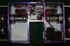
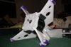
Ahhhh here we are. You might have wondered about the flower
reference in Belladonna. Wonder no more, here it is, the evil flower of
death. The Al braces hold it all together. You can see the EV nestled in
there snugly. Not shown is the rubber sheet that will surround the motor
and offer a little shock protection. Also not shown is the front plate which
holds the motor and the shaft bearing in place. This will take the shock
loads off the motor shaft. |
July 6, 2002
|
 |
Here are the drive motor controls courtesy of Dan at Team
Delta . What a great guy. I wrote him and asked if the relays were replaceable
on the smaller version of his dual ended switch (RCE220) , just in case
I blow one. I was concerned that the smaller one wouldn't handle the motor
current and the larger one (RCE225) wouldn't fit in the limited space I
had. I was considering trying to patch other relays into the switch or some
other crude hack, but Dan came through and suggested this. He sold me the
220 boards without the relays and the relays for the 225. Super cool, I
can fit the relays in elsewhere in the bot not having them tied to the board.
Thanks again Dan, you rock! |
 |
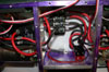
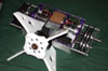
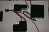
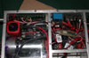
A shot of the bot from above showing the mounted relays and
boards. A piece of mouse pad cushions and insulates the boards which are
screwed to the back plate. I wired the whole thing up with some nice heavy
R/C car wire and 1/4" quick connect terminals all soldered together.
You can also see the drive battery. I decided to up the voltage to 12v to
get a little more speed and power. The original plan was to go with 7 cells
(8.4v) because I was going to use Traxxas XL-1's for speed controls, but
I needed the failsafes in the RCE220's so I opted for the higher voltage
because the relays can take it. |
 |
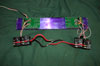
The center compartment of the bot houses the power distribution (the
terminal strip). The receiver also lives in here, but it's kinda packed
in later encased in foam. In the lower left is the voltage regulator,
Radio Shack 7805. It provides a steady 5v to the receiver and control
boards. I'm not terribly worried about dropout because it's gonna get
12v and the drive motors don't cause the battery to sag too much. I wrapped
it up in shrink tube to prevent contact with the chassis and stuck it
on with some double sided tape. On the lower right is the kill switch,
a removable link made of Sermos connectors. I chose to make it with 4
connectors so that I could also charge the bot through it, if I had just
used two it would have made emergency disconnect easy and cheaper, but
I couldn't charge the bot this way. There will be another set of these
for the weapon as well.
|
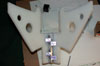 |
Having finished the electronics I turned back to the weapon.
First up were these little angle blocks. When I designed the bot I had planned
on the petals being lexan and only being 1/4" thick. The 3/8"
UHMW presented a problem in that I needed the Al strips to hold it together
and I had no place to put the bolts which I planned to drill through to
hold the pivot plates. Any hole that I would put through would not only
run into the Al strips but the bolts that held them together as well. These
angle blocks solve the problem nicely. |
 |
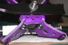
This is what those blocks hold, the weapon pivot bars. The
big bushing rides on a shaft that allows the weapon to pivot up and down
and therefore work right side up or upside down. Hence the concept of walking
invertable spinner. |
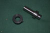 |
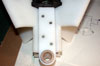
This is the weapon shaft itself. This took way too long to
make. It was turned from a chunk of 1-1/4" 1018 steel. Very beefy,
and very strong. Dunno what my problem is with turning steel, I think the
next time I do it, I'm gonna get me some of those nifty carbide tipped bits.
The bottom end with the slot is for the EV. Rather than muck about trying
to modify the motor shaft, I decided to adapt to it. The spring pin slides
down the slot and twists sideways at the top. The shaft is then locked with
a set screw into a flat that I need to file onto the EV shaft. The "twist-lock"
will prevent the shaft from coming off the motor, the set screw really is
only some extra insurance. On top of that goes some clutch material, the
blade and then the shaft collar pictured here. |
 |
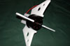
Here it is, almost done. A couple more bits to finalize and
or redo but this is pretty much it except for the blade and weapon batteries.
|
July 13, 2002
|
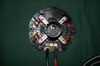 |
This is the brush holder for the EV warrior weapon motor.
I used a dremel to cut off the huge connector and soldered in these nice
12 gauge Deans Wet Noodle wires. Positive goes to the innermost track. I
also cut off the grounding tab on the right underside. Also not visible
are the capacitors I soldered both across the two terminals and from each
terminal to the case. I scraped the pain off the inside of the can so that
the caps could touch bare metal. That thing in the center is a shampoo cap
that I used to prevent the brushes from flying out. |
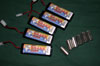 |
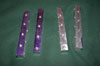
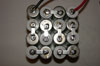
OK, here's my battery pack tutorial, for those who don't know
how best to make em. I chose these Duratrax Shark packs purely because they
were cheap (less than $10 apiece when you buy 6 from Tower).
On the right you can see the individual cells out of one of the packs. Although
you can't make it out there is clear shrink wrap on all of them. I got the
precut single cell shrink from Tower as well. If you plan on building your
packs out of bare cells like these, be sure and insulate them like this.
You can't have all the cell casings touching each other or you will wind
up with a lot of "magic smoke" |
 |
Now on to soldering them. To get results like you see here
you need a good soldering iron, not a gun. You will get much more consistent
results with an iron. I used a 40 watt weller from the Depot, at $15 not
too bad. Make sure that you use one of this wattage or a little more, 25
watts will not cut it for batteries. Make sure all your cells are clean
and free of any gunk. Then hold them together in some way. I used a small
dremel vise with a piece of plastic bag covering the jaws and slides to
prevent shorting. Heat up the iron and apply a small amount of solder to
the tip. Clean the iron on a wet sponge. You should clean the iron before
each connection that you solder. It sounds like a pain, but you will get
much better results this way. Put a battery bar (I used some Deans pro-bars,
you can use wire, but the bars are pre-tinned and much easier) across the
cell terminals and heat one end. The most important part of a good solder
joint is to melt the solder on the work instead of on the iron tip. You
can melt a bit on the tip to aid in heat transfer, but the strength of the
joint depends on the work itself being hot enough to melt the solder. Feed
solder in from the side of the bar until it melts and forms a small pool
around the bar and the cell. When the solder is hot enough it will flow
into a pool like this. As soon as this happens remove the iron. You only
want the iron in contact with the battery long enough to do this. Excessive
heat can damage the cells so use only the amount of time needed to properly
melt the solder. Use only rosin core solder for this as the acid core will
eat the metal away unless you clean it all off which is very difficult if
not impossible with batteries. It is also important not to move the joint
as it cools. If the solder joint has a hazy or whitish appearance you need
to let it cool and redo it. This is known as a "cold" joint and
it will fail, most likely when you least need it to. Your joints should
look like those in the picture above. This is 16 of the 22 weapon cells
that Belladonna will use. If you are new to soldering practice a bit first
on some heavy scrap wire before trying it on your expensive new nicads.
If you follow the tips above you too can make good looking and more importantly
strong joints for your all important battery packs. |
 |
I applied some stick on foam to the top and bottom of each
group of cells. Found the foam in the craft department of Walmart. The top
two packs are the weapon cells, 6 on the left 16 on the right. The lower
pack is for the drive, 10 cell for 12 volts. 14 gauge wire is used for the
drive and 12 gauge for the weapon due to it carrying more current. |
 |
Here are the packs in their places in the bot. Tight squeeze.
Seems to me on page two of this report I said something about not using
32 cells and having plenty of room in there. Famous last words indeed. It
does all fit though, albeit a bit snugly. All that's left to add are the
weapon relay and the RCE200B switch. I think I have just enough room in
the center for these. |
 |
I also did some work on the weapon pieces themselves. I added
the nylon skid tips to bring the weapon up just a tad so I can fit the blade
in correctly without hitting the ground. I also drilled and bolted the front
plate on. The blades are on order from a local lawn mower repair shop. It's
run by a friend of mines father, and he was able to help me find the exact
blades I need instead of having to cut larger ones down (all I could find
in stores were 16 inches and up which is too long) Big thanks to Mr. Vooris!! |
July 26, 2002
|
 |
I had got all the other stuff wired on the bot and did a little
testing. There were some "issues" with the failsafes. Even though
they would engage most of the time they would occasionally glitch after
the Tx was off. This was obviously unacceptable. A couple of E-mail's to
Dan at Team Delta had sorted out the problem.
Of course I should have known better than to trust the shack's part ratings.
They rate the 7805 regulator to put out an amp which would cover all my
power needs. What they forgot to tell me was that this was with an infinite
heat sink (hint : this is not actually physically possible)! In any case
here is how I squeezed in the receiver battery. You will also notice that
all of the aluminum ('cept for the gearboxes) has lost it's blue layout
dye. Although cleaning that crap off was on my to-do list, there was a "somewhat
regrettable incident" that motivated me to do it now. You see there
was a plastic bucket in the driveway. It was kind heavy. While testing I
noticed that the wind developed by the blade blew potential targets away
so I used the convenient bucket as a "backstop". I had not as
such checked to see what was in the bucket. While I was chewing on an old
CD rack the blade burst through the rack and consequently through the bucket.......which
was filled with at least 5 gallons of used motor oil. There was a rather
large spray of oil and a thud as my jaw hit the ground, and then the rest
of the oil poured out in a large stream all over the bot and flowing down
the driveway in a large puddle. Luckily virtually no oil got inside the
bot, and nothing touched any electronics. I completely disassembled degreased
and reassembled the bot that night. I did not get to bed until 5 a.m. It
was the robotic equivalent of sugar in the gas tank. So an important lesson.
Be careful what you hit, know what's inside it. It might be tempting to
break up things but beware that there are no hazardous materials inside
of things you are destroying, such as toxic metals in some electronic components
or potentially dangerous voltages inside of an old TV. At least the bot
wasn't damaged. |
 |
The other thing that Dan mentioned was this, that I was using
a single conversion Rx. Had I thought about it I experienced several jitter
problems with the servos in Morningstar and I had been using the same Rx.
I decided that instead of just upgrading to the far better dual conversion
receiver, I'd also go ahead and just get a better radio. I picked up a Hitec
Laser 6 channel radio from Tower. What a great radio for robot combat especially
in the lower weight classes. It comes in 75mhz, with a dual conversion receiver,
dual rates, and it also has onboard mixing! Best of all it was only $150,
just a bit more than the Futaba 4vf which has no mixing, dual rates or 6
channels. It's not computerized but you can't beat the price. This pic shows
the receiver wrapped in it's protective blanket for shock protection. Above
to it's right and left are the removable links for drive and weapons. The
blue box in the lower right is a 12v relay from the shack. When I had to
go with the separate Rx battery I wanted to avoid having a flimsy Rx switch
to get turned off in the heat of battle. I just connected the relay coils
to the 12v drive rail (which is switched via the drive removable link) and
presto, instant easy on and off for the radio. In the lower left is the
new home of the terminal strip which distributes the drive power. Underneath
the blue relay is the 70 amp one for the weapon. It was a tight squeeze
to get all that in there especially with all the connectors. |
 |
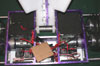
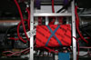
This may be the last thing your bot sees! Here is the blade,
which is actually two lawnmower blades stacked together. Haven't weighed
it yet but I think it will be under 24lb. You never know, if I have the
weight I just might stack all three on there. In any case this thing is
quite frightening. As I said before the wind off the blade was powerful
enough to blow most things away from it. The shaft collar that you can see
holds the blades against a piece of clutch lining material that I got from
McMaster. I tighten the shaft collar down with a pair of C clamps to get
the preload on the clutch washer. The whole assembly allows the blade to
slip a bit under hard shocks which will help prevent damage to the motor.
I also took the time to take apart the weapon (for the 20th time grumble
grumble) and dye all the parts purple with some RIT fabric dye. 4 hours
in a 250 degree oven and the UHMW took on the perfect shade. |
August 12, 2002
|
| |
Well, Belladonna is complete and ready for the House of NERC
event this upcoming weekend. Not all that much was done since the last entry.
Current weight is approximately 22.5lbs a bit higher than I would like,
but with a whole lot of room to loose weight. Since I knew that at this
comp I would be able to carry the extra weight I simply didn't follow through
on all my weight saving measures and in fact added a couple of things I
would not have done (like the double blades). To finalize construction the
rubber belts were secured to the feet with some double sided servo tape.
The leg shafts were trimmed to be flush with the sides. I would have left
them a little long, but the sides were at 18" wide which is the maximum
allowed width at NERC events. The other mod was to the gearboxes. Durring
testing last week one of the motors smoked itself. Wondering why I pulled
apart the gearboxes first. It looked as if the nylon gears in the first
stage had worn down a bit and might have caused some missalignment and binding.
To fix this I put the steel gears from another set of gearboxes in the first
stage. I had to trim them down a bit on one side so that they would be as
thin as the nylon ones. Unfortunately there was still some binding in the
legs causing the motors to stall. In a fit I pulled apart the leg mechanism
totally and eventually found the trouble. When I had re-cut the shims for
the leg bearings I got lazy and only cut 4 for each bearing. The logic was
that the bearings had "run in" some and would only need 4 instead
of the original 5. This was wrong. When I put all 5 back in the binding
problems dissapeared and my problems were over. The last thing to do was
to apply the cool graphic Kirstin helped me make. I'll put it up here when
I can get the pictures onto the computer I am now using for web access (It's
a big mess, I no longer have internet at home, soon to be corrected though.) |