![]()
Related Electronics
![]()
INTRODUCTION
The goal is to make a fully integrated electromechanical system that involves active electronic compensation to push the limit of this budget speaker.
![]()
DESCRIPTION
This part is divided to two main sections, mainly the subwoofer and satellites.
![]()
LINKWITZ TRANSFORM
The subwoofer F3 as calculated earlier was 60hz. This is not low enough for reasonable low frequency reproduction. A Linkwitz Transform circuit is used to lower the F3 to 30hz and Qtc to 0.6. Unbelievable but true is that the group delay is lowered as well, as though a much larger woofer were being used. Of course there is no free lunch, higher amplifier power and woofer excursion cause greater nonlinear distortion. The graph below shows the actual(blue), corrected(green) and compensation(red) curves:
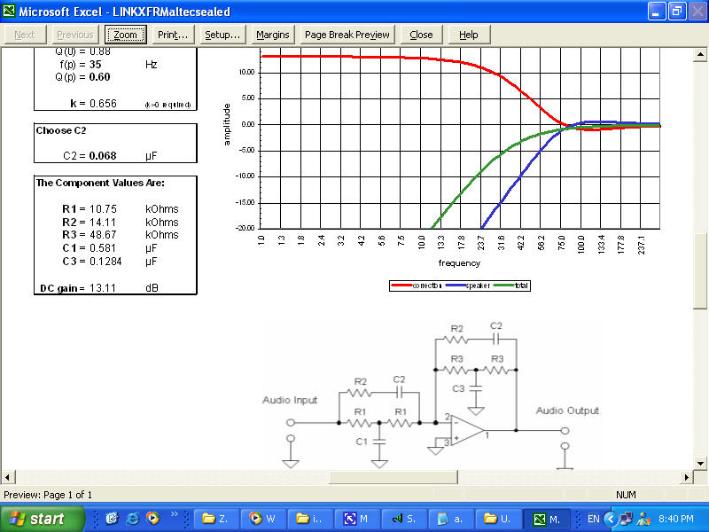
A maximum DC gain of 13db requires a ludicrous 16x amplifier power. But in real life this is not true, as most music do not contain high levels of bass. I will not bore you with any studies done here, but suffice to summary that about 4x the power will be plenty. This will be left as a later exercise.
With this much of DC gain, care must be taken to roll off subsonic frequencies to prevent damaging both woofer and amplifier. A subsonic high pass filter will cause phase shifts resulting in increased group delay, which is undesirable. I might use the DSP correction to truncate subsonic frequencies but that also will be left for a later exercise.
![]()
BAFFLE STEP COMPENSATION
Under construction!!
![]()