![]()
Tripath Class-T switching amplifier
![]()
INTRODUCTION
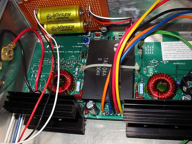
This amplifier is built around the Tripath TA-0104 evaluation module. Only a few modifications are made, described below.
![]()
DESCRIPTION
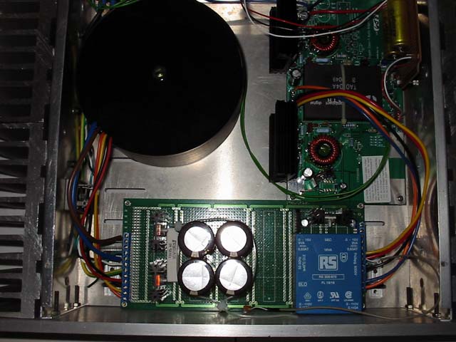
Since most of the circuit is done, I concentrated more on the power supply. I used a 500VA toroidal transformer and 6*6800uF@80v Panasonic Audio grade capacitors. The rectifier is made up of high speed 20A diodes from ST semiconductor (cheap). I'd like to try HEXFETS from IR, but they are too expensive. The 5v logic supply is not critical, and is made up of a simple board-mount transformer and generic LM7805 voltage regulator. The inrush current is suppressed by a 3A thermistor. A EUROcard pcb is used to hold all these components together.
I changed the input coupling cap to a 0.47uf Jensen paper-in-oil capacitor. These are the cheaper(!) range with silver leadouts, but already burn a hole in my pocket (US$15 each). The original 1uf electrolytic capacitor (yuck!) sounds less transparent than the Jensen, but to my surprise actually has better bass. I also increased the gain of the amplifier to 20dB by replacing the input resistor to a Holco 38.5kohm resistor.
Output muting is achieved easily by wiring the mute trigger to the unused pole of my power switch. Easy, effective, and avoids use of output relays. I made use of the wires on the module, resulting in a neat and short signal path. For example, the output wires are soldered directly to the output terminals, all power supply lines are wired directly to the power supply board, and the inputs are connected via silver plated Teflon wires soldered to the input terminals.
The power supply is essentially unloaded when idle, due to the very low power consumption of the amplifier module. The voltage rails reach a maximum high of +/-83vdc, usually late into the night. Luckily there were no problems with the smoothing capacitors (rated 80vdc). This works out to about 300watts per channel, according to Tripath's datasheet.
![]()
SOUND QUALITY
The most notable quality of this amplifier is its bass quality. It is tight yet authoritative. However, it is slightly affected by the Jensen coupling caps. Maybe a Hovland cap would sound faster. The treble is pretty refined, an unexpected result considering this is a switching amplifier. What I find wanting about this amplifier is its recessed midrange. The overall impression is a lean sounding amplifier, quite a contrast from the Pass Labs designs.
![]()
FURTHER TINKERING
Well, an unfortunate power surge had taken out the -12v supply on board, namely the LM2594 switching regulator and some associated components. Since I was already having a trying time removing the components (the ground plane was exceptionally difficult to work with), I decided to make some mods as well. A quick check showed that the easiest way to gain improvement was to replace the output mosfets. The original mosfets are the STW38NB20. Its desirable characteristics include a low on-resistance (Rds) of 0.065ohm and high drain current (Id) of 38A, at the expense of a not-so-ideal gate charge (Qg) of 95nC. I looked at the IRF240 which where lying around in my parts bin, and found that they were a (almost) perfect drop-in replacement. The specs show a lower Id of 20A and Rds of 0.18ohm, but a pleasant Qg of 70nC.
What do all these figures mean? Well, a lower Id is obviously going to reflect in less maximum power output, but that is not my main concern. A higher Rds means lower efficiency, but even then the amp dissipates less than my preamp at idle, so no concern there. A lower Qg puts less stress on the drivers, which lowers switching losses and (maybe) distortion.
Well, proof of the pudding is in the listening. Usually changes to switching amplifiers cannot be approached in the same way as linear amplifiers, but knowing what parameters to look out for will bring desirable changes. As expected, the sound took on a more organic quality, with high frequencies sounding less detached and almost hash free. This resulted in a more 3D quality to the soundstage, though I did notice a slight loss of immediacy (aka PRAT) and bass control. But hifi is all about compromises, and till today I still believe I made the right choice.
![]()
FUTURE MODS
The 0.47uF Jensen input caps I use create a low frequency pole with the input stage at 10hz. This is believed to be causing certain phase shifts and a corresponding muddying of bass frequencies. I'm also suspect of the sloppy input stage which is a poor excuse for cheap and shoddy amplifiers. A servo input stage with proper level shifting that extends to almost DC would be in order - when I have the time. Stay tuned!
![]()
PICTURES