 |
|
|
|
|
|
|
|
|
|
|
|
|
|
|
|
|
|
|
|
|
|
|
|
|
|
|
|
|
|
|
|
|
|
|
|
|
|
|
|
|
|
|
|
Features and Power Control Circuit |
|
|
|
 |
|
|
|
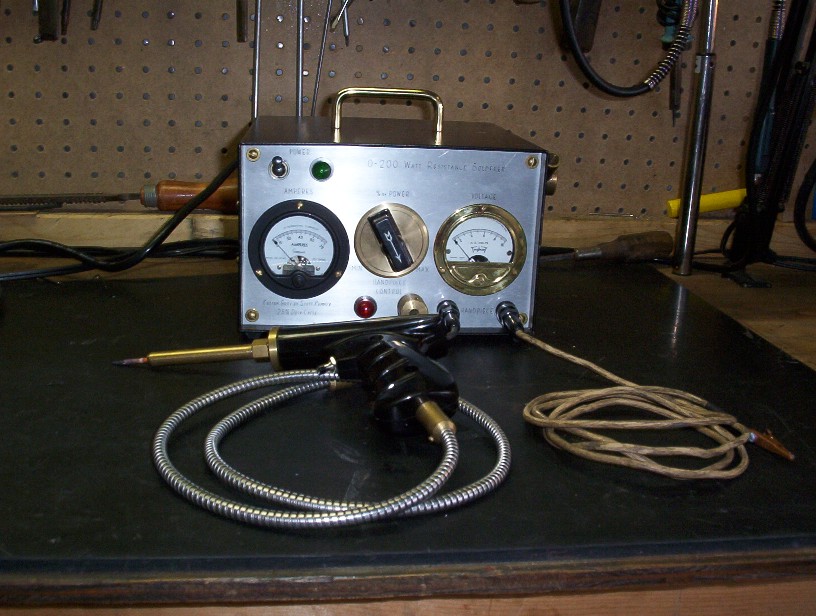
Features include:
� 200 Watt maximum output
� Infinitely variable output
� 25% duty cycle
� Electronic power control
� Built in Ampere and Voltage meter
� Custom turned brass hardware and fittings
� Onboard cooling fan
� Built with used and salvaged parts
� Modular construction |
|
|
|
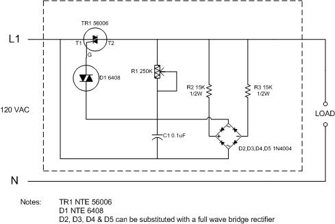
The power control circuit: |
|
|
|
 |
|
|
|
Schmatic 1 |
|
|
|
TR1 NTE 56006 Bidirectional Triode Thyristor 15A (Triac)
D1 ECG 6408 Bidirectional Trigger Diode (Diac)
R1 250kohm potentiometer �� shaft panel mount (Pot)
R2, R3 15kohm � watt resistors
D2, D3, D4, D5 1N4004 diodes (full wave bridge)
C1 0.1mF Capacitor
Circuit Board Small prototyping board
Heat sink Drilled for TR1 (TO-220 package) |
|
|
|
The hardest part of the build was to find and / or design a circuit that could handle the load and still stay with in my budget. This little circuit does both. It varies the power output with one potentiometer (variable resistor) R1. R1 is a panel-mount �pot� with a �� shaft for a knob. It varies the power by synchronous triggering across the triac. On the triac TR1, terminal T1 is input, terminal T2 is output and G is the gate. All the parts were readily available form my local electronic supply store and built on a point to point prototype circuit board. This is a simple but a reliable circuit which will handle 15 Amps but in my unit it only has to about 4 Amps since I am controlling the primary windings of the transformer. On a side note, this circuit can be adapted to numerous other applications where controlling power is a requirement as in a lamp dimmer or putting a variable speed feature on an AC motor like a drill. |
|
|
|
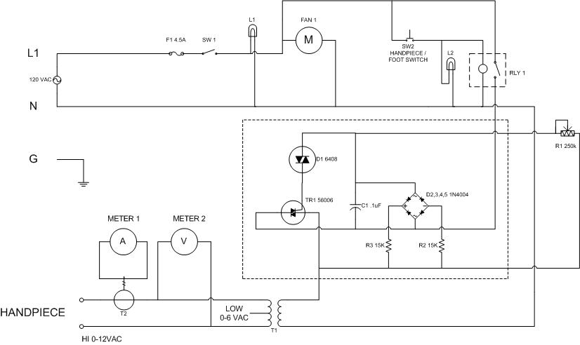
Schematic incorporating the above circuit: |
|
|
|
 |
|
|
|
Schematic 2 |
|
|
|
F1 4.5 Amp Glass Fuse
SW1 SPST toggle switch (power)
L1 120VAC Green Lamp (power)
FAN1 120VAC 4� Brushless Cooling Fan
SW2 Hand-piece Control (small push button) / Foot Switch
L2 120VAC Red Lamp (hand-piece control)
RLY1 Small 120 VAC SPDT relay
T1 120 � 12 VAC C.T 5 Amp Filament Transformer
METER1 0 � 10 2-��AC Volt Analog Panel Meter
METER2 0 � 75 2-�� AC Amp Analog Panel Meter
T2 Current Transformer matched to Amp meter |
|
|
|
As soon as SW1 is turned on, L1 and FAN1 come on. I wanted to do all the switching and control on the primary side of T1. Even though the voltage is higher (120VAC), the current would be much lower. The circuit is switching the incoming AC into the power control circuit thru relay RLY1. In turn, RLY1 is being controlled by SW2. The current draw of RLY1 is very small so this allows SW2 to be compact allowing mounting almost anywhere as in my �pistol� like soldering gun (carbon rod holder). I mounted SW2 in the trigger position eliminating the need for a foot switch. With my tweezer set up, the floor switch is still employed. L2 comes on with RLY1 and is mounted to the front panel. Voltage is fed from the power control circuit to T1. The highest current draw that the power control circuit with RLY1, FAN1 and T1 at full power is approximately 4 Amps. Since all this is passing thru RLY1, RLY1 should be rated for at least 10A. I rated F1 at 4.5A. On the output of T1, a voltage meter and an amp meter are installed. This gives me a good idea of the wattage output for any soldering operation. For instance, if I read 2 volts and 20 amps, using Ohm�s law:
Power = Volt x Amp
Power = 2 x 20
Power = 40 Watts
METER2 (volt meter) is connected across T1 while METER1 (amp meter) is connected to T2 (current transformer). T2 was constructed from four 2� steel washers welded together to make one thick �doughnut� core. Light gauge wire was wrapped thru the hole and around the outside. I wrapped about 60 turns of the wire and connected each end to the meter terminals. The output of T1 was also wrapped about 6 times thru the hole. This matched the transformer to METER1 which brought it very close to the actual output as tested by my Fluke meter. With power set to MAX, I can pull about 50 amps @ 4 volts which is exactly 200 watts! Interestingly enough the primary side of T1, draws about 4 amps on MAX. So again using Ohm�s law, this comes to 480 watts (120volts x 4amps). With 480 watts going in and only 200 watts coming out the rest must be loss. A lot of this loss is dissipated by heat so that�s why I found it important to keep the unit as cool as possible with the cooling fan and rate it at 25% duty cycle. For every minute of operation I let it �rest� for four all though a typical cycle only lasts a few seconds. I also have a good size heat sink on TR1. Also of note, T1 has a center tap. If the center tap is used, the output drops to about 6 VAC. One item I am meaning to test is the operation on the lower voltage to find out if there is a performance gain. |
|
|
|
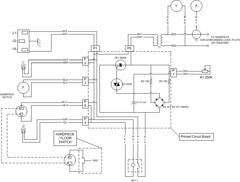
Schematic of the finished unit |
|
|
|
 |
|
|
|
Schematic 3 |
|
|
|
 |
|
|
|
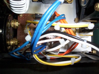
This picture and schematic 3 show how I used the circuit board as a central connection point and colour coded the wiring. All external devices plug into the board. This will allow easy removal and service of the board and the outboard components. This feature also permits easy modifications! |
|
|
|
|
|
 |
|
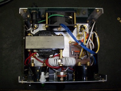
And this is all the components put together. I made a �false� bottom plate so every time I wanted to change the internal configuration, it was just a matter of replacing it rather than drilling new holes in the bottom and abandoning the old ones. Here you can also see the custom made current transformer (T2) wrapped with the light gauge white wire. The red wires leading from the large black transformer (T1) are a heavy 10 gauge (to handle the current load) and are connected to the binding posts on the front panel. |
|
|
|
|
|
OVERWIEW HOME CONSTRUCTION |
|