 |
|
|
|
|
|
|
|
|
|
|
|
|
|
|
|
|
|
|
|
|
|
Construction |
|
|
|
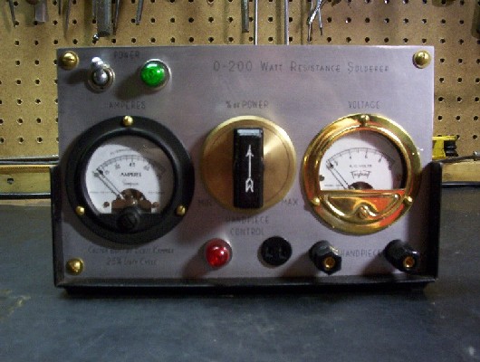
One of the few items I bought new was a project enclosure. It�s a good sturdy case with removable front and back panels. Since I wanted to add the amp meter (METER1) after I built it the first time, I needed to replace the front panel. I had a custom engraved panel made with all the labels. I used a retro font to give it the classic look. I filled in all the lettering with black paint so they would stand out as shown in the picture below |
|
|
|
 |
|
|
|
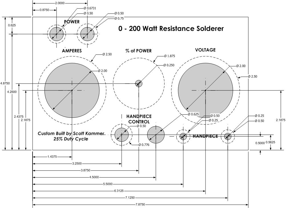
This was complemented by a custom turned adjustment knob in the center. The voltage meter (METER2) on the right was a great find. While rummaging thru some old meters at a second hand store I found this little gem. It was painted black but scratched badly. I was about to repaint it when I thought it might polish up well. I wish I could find a matching amp meter (METER1) as well. The hand-pieces plug into the binding posts on the lower right hand side. I am using normal banana jacks soldered onto the leads. The hand-piece/foot control switch (SW2) plugs into the 2 prong receptacle and the red lamp (L2) lights when activated. And finally the power switch (SW1) is located on the upper left hand side along with the green lamp (L2) which lights up when the unit is turned on. Diagram 1 was the print I sent to the engraver. |
|
|
|
 |
|
|
|
Diagram 1 |
|
|
|
 |
|
|
|
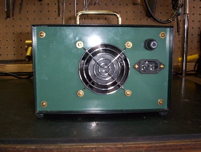
The rear view shows the cooling fan inlet with guard as well as the power cord inlet. Above the inlet is the fuse holder. This picture also shows the top installed with the handle. This is just a 3� brass drawer pull from a local hardware store |
|
|
|
|
|
 |
|
|
|
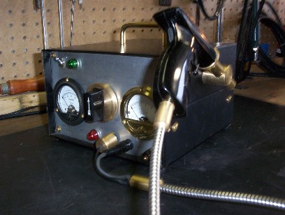
On the right hand side of the station is a holder made from solid brass stock for the soldering �gun�. It keeps it out of the way and protects the carbon tips. |
|
|
|
|
|
FEATURES AND POWER CONTROL CIRCUIT HOME HANDPIECES(SOLDERING GUN) |
|