|
|
This details the adjustment mechanism from the side. In practice, the adjustment is limited by the size of the square tubing. I could only find 1 1/4 inch tubing, so the range of adjustment is 1/4-inch in and out and 3/8-inch up and down. Because of leverage, adjustments on the outside of the ring create very fine movements in the center. Springs (not drawn) create opposing tension against the adjustment screws so the adjustments can be made and then locked-in with a lock nut. These small adjustments should be adequate to accurately position the secondary mirror as long as great care is taken to accurately position the mirror in relation to the eyepiece holder in the first place. Here are some pictures to demonstrate the motion of the adjustments: |
|
|
|
|
|
|
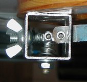
spider vane is UP |
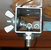
spider vane is DOWN |
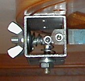
spider vane is IN |
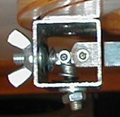
spider vane is OUT |
|
|
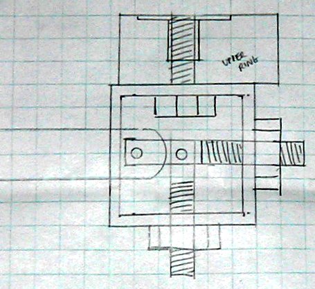
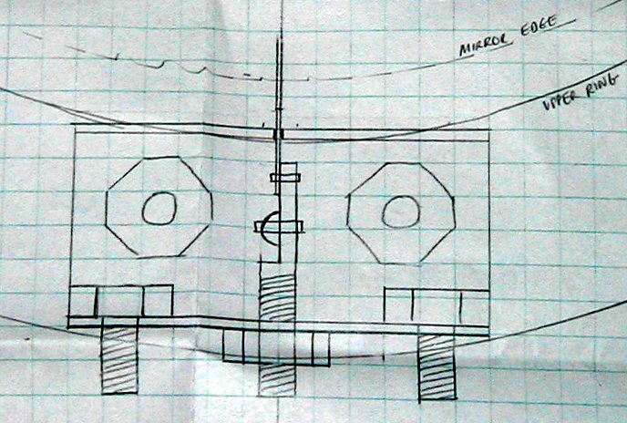
This view shows the rig from above in relation to the ring and the mirror. The truss attachment screws are seen pointing down on the left and right. In the pictures below, they are shown with wingnuts attached. The spider adjustment screws (center) are sawed in half and joined in a pivot. The spider vane (a hacksaw blade) is joined by a second pivot and extends through a slot in the rig that keeps the blade perpendicular. . |
|
|
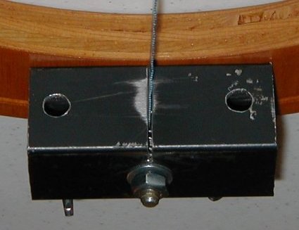
Viewed from the inside of the ring, you can see the slot where the spider vane is held perpendicular. The vertical adjustment screw/nut is seen in the center. The two holes are used to tighten the truss screws on the outside (not seen in this picture). Since the screw holes on the other side are tapped (just like a nut), the screws are threaded from the inside to the outside to allow the truss rod holes to be held in place by wingnuts. |
|
|
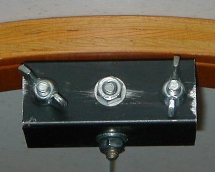
Viewed from the outside of the ring, the truss screws can be seen with the wingnuts attached. The vertical adjustment and horizontal adjustment screws can be seen in the middle. In application, the truss rods would be held in place by the wingnuts, but the adjustment screw/nut is still accessible from the outside of the upper tube assembly ring. |