Created by Joselito Kuizon Jr.
2-3. Design Features
Design feature allows you to create solid features whether cuts or protrusions.
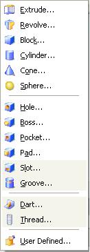
You can select the icons or from the Insert > Design Features Pull-Down Menu. Below are the design features in UG NX 3.0:
2-3-1. Extrude
To create extrusions, you need an existing face, edge, line, curve or a sketch.
You have the option to select the object first then click on the extrude icon or select the extrude icon first then the object to extrude.
A dialog box will then prompt you to select the options to use.
![]()
by clicking the first button, an options dialog box will prompt you for inputs for the object to extrude.
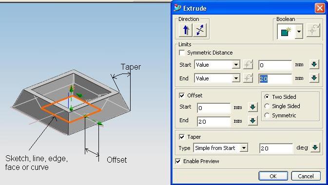
Entering the appropriate values will result in the creation of the extruded feature/object.
2-3-2. Revolve
Just like extrusions, revolves also need an existing face, edge, line, curve or a sketch.
And also just like extrusions, you have the option to select the object first then click on the extrude icon or select the extrude icon first then the object to extrude.
Select the Revolve icon ![]() or from Pull Down Menu: Insert > Design Feature > Revolve...
or from Pull Down Menu: Insert > Design Feature > Revolve...
If an existing face, edge, line, curve or a sketch is not selected yet, a dialog box will prompt for the required object.

Select the existing face, edge, line, curve or a sketch, in our case a sketch, and click Ok.
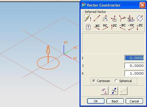
A seconde dialog box will prompt you for the axis of revolution.
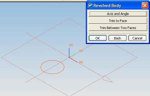
Select the Datum Axis that you want to use as axis of revolution.
If you decide to use another location of the axis of revolution, a third dialog will prompt you for the new location.
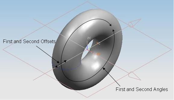
A fourth dialog box will prompt you for the start angle, end angle, first offset, and second offset:
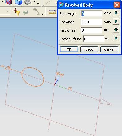
A zero offset will result in a solid revolved feature.
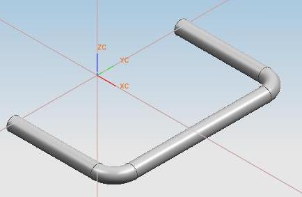
2-3-3. Sweep
A sweep is created by generating a cross-section along a path. You will need an existing face, edge, line, curve or a sketch, one for the cross-section and one for the trajectory.
The cross-section must be normal to the trajectory.
To create a sweep
along guide, click on the Sweep Along Guide icon ![]() or from the Pull-Down Menu: Insert > Design Feature > Sweep Along Guide...
or from the Pull-Down Menu: Insert > Design Feature > Sweep Along Guide...
A dialog box will prompt for the Section String:
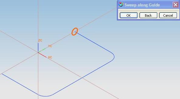
Select the cross-section. In our case, the circle, then select Ok.
Another dialog box will prompt for the trajectory. Select the sketch then click Ok. You can enter the offsets for the feature.
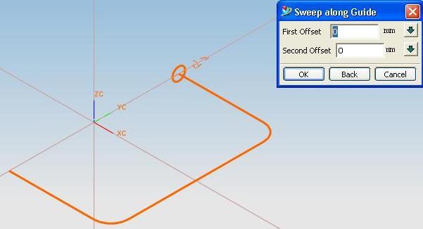
A sweep feature will then be created.