Created by Joselito Kuizon Jr.
To activate Assembly mode in UG NX
3, click on the Assembly application icon ![]() or from the Pull Down Menu: Application > Assemblies.
or from the Pull Down Menu: Application > Assemblies.
To de-activate, click the icon again.
2-3. Adding Components
To add components, UG NX 3 must first
be in Modeling Mode ![]() .
.
To add an existing component, select
the Add Existing Component Icon ![]() or select from the Pull-Down Menu: Insert > Components > Add Existing...
or select from the Pull-Down Menu: Insert > Components > Add Existing...
A dialog box will prompt you for the component to add to the assembly:
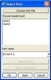
You may click on the listed component(s) to add and click Ok, or click on "Choose Part File" button to load the component to add if it is not on the list.
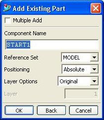
A second dialog will prompt you for Reference Set, Positioning and Layer Options. Select the appropriate options and click Ok.
A third dialog will prompt you for the positioning. Enter the location where you want to place the origin of the component. Click Ok.
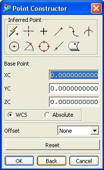
Since this is your first component, the component will automatically be placed on the designated location.
To add a new component, select the
Add New Component Icon ![]() or
select from the Pull-Down Menu: Insert > Components > Add New...
or
select from the Pull-Down Menu: Insert > Components > Add New...
A "mini" dialog box will prompt you for the object to copy or move. Click on the "Check" mark.
![]()
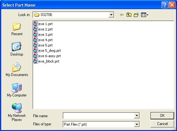
A dialog box will prompt you to create the part file. Enter the file name and click on Ok.
A second dialog box will prompt you for the Component Name, Reference Set Name, Layer Options, and Component Origin. Enter the appropriate values and click Ok.
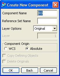
The empty component will then be created and placed on the location set for the component.
2-4. Constraining Components
There are eight constraint types in UG NX3. Combinations of these eight types are used to constrain components in an assembly.

Assembly constraints apply only after adding the first component.
To constrain a succeeding component
to the first component (s), Add an existing component by clicking the Add Existing
Component icon ![]() .
.
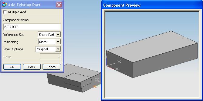
A dialog box will prompt you for the component to add. After selecting the component, click Ok.
A second dialog box will prompt you for the Component Name, Reference Set, Positioning, and Layer Option. A component preview is also available. After entering and selecting the appropriate values, click Ok.
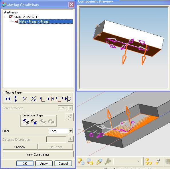
A third dialog box will prompt you for the mating conditions.
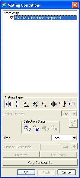
Click on the mating type desired first. Select (click) the face of the component to be added on the component preview, then click on the face to be mated of the first component. Click the Apply button to enforce the constraint.
The order of selecting the faces is important. To reset the selected faces, click on the first button of the Selection Steps button group.
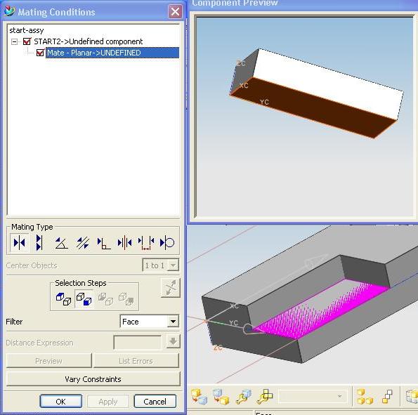
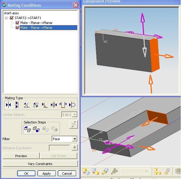
Select the next faces to mate. Select the face of the component to be added then select the face of the first component.
Select the third set of faces to mate. Follow the steps outlined above for the first two sets of faces to mate.
Be sure that the constraints set do not conflict with each other. The List Error Button will be activated if there are errors. Clicking on this button will show you the list of errors.
If there are no errors then you may Preview the assembly by clicking the Preview button. You may also vary the constraints.
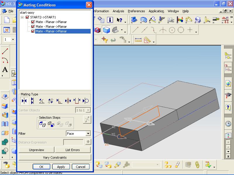
Click Ok TWICE to finish the assembly process.