 |
| My cohort Ari Schrager did an anode modulator with 5KV swing. He uses torroidal-ferrite trigger-transformers to couple "start" and "stop" trigger-pulses to push-pull complementary high-voltage switches. Each switch is comprised of 10ea 1KV Field Effect Transistors (FETs), all driven in unison. Two adjustable Bertan-brand high-voltage supplies serve as power rails. Both get switched to a single output terminal, in an alternating fashion. Ari's method uses the "memory effect" intrinsic to field-effect transistors. The glass encapsulated gate has so much capacitance it won't budge without a show of force. In standby or CW, periodic "refreshment" keeps switches on. At state-change, trigger pulses fan out to drive respective devices. Start-pulses drive a shot of charge into respective FET-switch gate-capacitances via diodes. Stranded charge effects lingering device conduction. Stop-pulses drive stop-pulse-FETs. Each discharges the gate capacitance of a respective switch FET. Start pulses that drive the 10-FET "pulse" switch-group also drive stop-pulse-FETs in the conplementary "tailbiter" switch group. In this way, it resembles the work of Arnold Feldman, in the Cober 502 grid modulator. The Cober 502 input jack uses magnetic trigger pulse coupling: it has a ~20 turn primary winding on a torroid, driven through 51 ohms. Identical but floating, the receiving-end couples to the sending-end via induced current in a closed loop of high voltage wire. This provides high voltage isolation. Positive and negative output spikes trigger pulse or tailbiter conduction respectively. Mr. Feldman uses ferrite torroids like Ari's to trigger discreet cross-coupled latches made from high-voltage power transistors. These drive respective switch-tube grids directly. Winding polarization toggles grid-drivers oppositely. The 502 delivers 2KV swing at 100 KHz into 100 Pf with 300 nanosecond transition times, with 0-100 milliamps DC loading. Mr. Feldman uses low-cost glass planar-tetrodes designed for mobile UHF transmitter duty. Output dV/dT roughly matches Ari's. As a test-bed, it proves ferrite trigger-pulse coupling-transformers will survive 2 KV swing over a 50 year span. |
| The Hewlett Packard 2601 high dV/dT optoisolator proved fickle doing tetrode grid drive signaling. Dave Harpe researched the phenomena and coordinated with HP. His test jig, a grid modulator, was instrumental in HP's development of the 2611 optoisolator. It beat a published 10 KV per microsecond common mode rejection spec. Downgraded to 5 KV/ microsecond, batch variation was a problem. A better product couldn't be offered. 3 KV grid modulators push the practical limit of opto-isolator design. My 5.5 KV requirement begged for another answer. Ari rendered the above moot with his transformer coupled drive scheme. He eliminated the power supply requirement for individual switch decks too, all in one fell swoop. |
| I was uneasy with Ari's arcetecture for various reasons. Refresh-cycle transients radiate to some degree. This would compromise the noise floor. Ari's rise and fall times missed my spec by a factor of three. But most pressing in my mind was high likelyhood of corona in the "start" and "stop" trigger pulse transformer windings. Ari only did 1 KHZ. Using hookup-wire windings--tightly-wound onto small ferrite cores--he appears to have achieved 5 KVAC isolation. But ferrite doesn't have high dilectric strength. With his ambitious 90-day schedule, there probably wasn't time for partial discharge testing. People unknowingly "get away with" all kinds of things. "Knowing better" has its corrolary: Murphy's Law. Ari's design would only produce blue glow and smoke for me. He's the better man. Knowing better hasn't advanced me one bit. But I'm rightly leery. Corona flairs up. Who knows why. I only know that gag isn't getting me again. |
| Reynolds brand spark gaps protect ETM grid and anode modulators. This had a 7.5 KV gap between the output terminal and the box. |
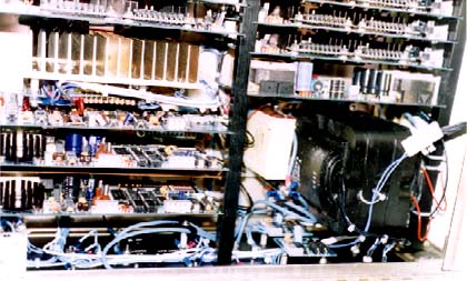
| The two identical boards in the lower left are called Interface Perameter Reg Amps. Wendel's regulator is the outgrowth around the heatsink. Behind that, a two channel 16 bit D/A convertor provides dual 0-10 V precision adjustable reference outputs (one traditionally controls the on-board regulator). The TTL group in the middle clocks serial data into a shift register from a fiber optic link. Embedded in the data is control for: D/A convertor outputs, input multiplex switching, and input range. Each incoming data arrival triggers readback from a 16 bit A/D convertor. Measurement data exits the board in serial form via fiber optic. Input channels include 4 ea.10 VDC diffirential inputs and 3ea.single ended inputs. One shorted input channel measures input offset for subtraction. |
| Anode modulator development considerations |
| Historic context |
| Device limitations |
| Jeff's Choice: |
| For switch-deck power, I called out transformers like my prototype for the grid box, but rated double voltage. I ran secondaries to switch decks telegraph-pole-style, via machined delrin racks. |
| Why not use Ari's method? |
| Do corona tests leave you feeling sleepy the next day? Now you can view corona in broad daylight! Solar blind UV viewer |
| Ron Swanson's driver; Gunnar-Wik's iso/xfmr, FET, zener protection; and HP fiber-optics form switch elements. |
| Richard Ziskowski's quasi-peak-voltage metering made it in, just in the nick of time. |

|