 |
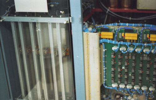
| Jake found .01 % accuracy, one megohm, zero temp. coefficient resistors. He made boards sporting fifty each, seriesed. Housed inside 4" copper-foil-shielded PVC pipe; one assembly can do 25KV metering; we use two for 50 KV. Add NP0 capacitors and you've got a compensated feedback divider. Hooray Jake! |
 |
| Feedback and meter dividers |
| Ion pump power supply: 0 to +4KVDC |
| By Bertan |
| Balvier Thind headed up corona control for dividers. |
| 189KVA VVT |
| Peschel by Hypotronics |
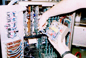
| This is a shot from an expose I did, illustrating various disassembly/reassembly sequences. |
| I'm shown removing the anode pulse top regulator heatsink, also hub of local referencing, frequency injection, current metering and surge supression. |
| Anode Modulator for the CEC program |
| The regulator board ground-testpoint is at supply output potential (don't get bit). That's ETM grid-box tradition. |
| A 10 KV 100 ma Bertan supply (not shown) provides bias voltage. The -500 V pulse-top shunt regulator draws preload current from it too. The Bertan supply current rating presently limits full-swing pulse repetition frequency to 50 KHZ. It'd be nice to have 500 milliamps to play with. An IR thermographic camera would be ideal for establishing safe limits. The supply is presently modified to put out about 170 MA ( the manufacturer said we are well under full voltage so we can have more current. I think I had to lift a diode or zener and feed extra refrence voltage from the perameter board reference output. Specified at 5,5 KV swing, pulse and tailbiter switches are each rated 7.2 KV. Rise and fall times are each less than 300 nanoseconds (measured at the 10% and 90% points, driving 100 P.F capacitive, 10MA DC bias current, and 50 MA DC pulse-top current). Pulse-top ripple is less than 5 millivolts RMS. Pulse to pulse jitter is less than 500 picoseconds. Overshoot reduces to less than one volt within 250 nanoseconds. Tektronics probes lack the needed accuracy for taking the overshoot measurement. This was one of ~ten things I balked at upon first reading the spec. As it turnes out, there is a way: anode voltage deviation directly translates to velocity modulation in the beam, translating directly to phase modulation of output power. so it can be done |
| We weren't allowed to buy power supplies for the longest time. Chuck said we build them, buying them admits inability to do so. But Bertan supplies gained acceptance with time. Reliable and cost efficient, I wanted one for bias rail duty. Jake said I had to make due with a unit having a case-connected return lead. I'd wanted both leads floating but figured I'd probably be fine up at cathode potential: the 115 VAC is isolated for 50 KV anyway. What could it hurt? Somewhat of a miscalculation, distributed capacitances in the multiple loads made the situation somewhat tenuous. Common mode line noise emanating from the Bertan supply was obnoxious. I'd counted on floating it five ohms away from box potential on "anode common." I ended up wrapping #16 twisted-shielded pair onto a four-inch OD. tapewound orthinol toroidal core (until it was full). I slapped it in line with the primary power wires to the Bertan. That quieted the high frequency noise. Problematic 60 Hertz common-mode ripple current traced back to the Bertan too. Capacitors in the line filter were responsible. Absolutely unbalanced, "hot" and "neutral" line-wires met with symmetrical bypass capacitors to the chassis of the Bertan. Running with a balanced AC line proved key. For referencing, I started with a rheostat across the line, wiper tied to the box. I nulled anode pulse-top-rail ripple by adjusting the rheostat. The finished work sports 2ea. 100K A&B 2W CC resistors, in the line-wires connecting an A&B 2-Watt "ripple-nulling" pot. Noteworthy of the change, our AC is now soft if inadvertently shorted to a chassis. All floating AC leads get varistors, to each box served, at each point of entry. |
| We also went with zero temp coefficient current-shunt resistors, .05% tolerance, paralelled, distributed, heatsink-mounted; with each shunt rated for ten-times actual dissipation. All sport thyrite and spark gap protection. Average current shunts also got an electrolytic bypass cap. |
| .01% 50KV NIST-traceability never materialized for us. But we went head to head with a Ross brand divider, also touting .01% tolerance parts. Combined error suggested grounds for rejection only if entirely attributable to one "offending" meter. The greater likelyhood was of two successful good-faith attempts. I was pleased. |
| Tired of re-tourquing high-Amperage AC connections? Perhaps Belville brand washers are for you: stackable--with dished spring-steel construction--they provide uniform contact pressure with temperature cycling. I use one per side. |
| modulator service bypass sw. |
| panel open bypass |
| 24V PS for external accessory reset> |
| RC status readback boards |
| Watchdog |

|
| brush assy. |
| pulse reg. | |
| bias ref. ps.> |
| |switch cards| |
| grid 3.3KV Xfmr. |
| pulse fault |
| anode modulator pwr. |
| grid step start |
| grid final |
| pulse top reg pullup/ |
| output resistor |
| bias |
| pt |
| ps |
| boost |
| pulse |
| top cap |
| bias loadbank |
| rail cap |
| steering/ detect. |
| SSRs |
| top amp |
| bias pulldown |
| tailbiter |
| pulse |
| IP |
| S&H |