 |
| Anode Modulator pulse top p.s.+10 V to -500 V 50 KHz Bias supply range 0 to -5,500 V |
| Grid Modulator pulse top p.s. 0 to +3 KV WRT bias 100 KHz Bias p.s. -50 V to -3 KV |
| Jake did a fine job on this heater box. I just razzed him about all the standard bum actions. He redoubled our effort in every way. It's built to beat the +/- 15% line variation specification. It has a footlong-chimney heatsink and sports frequency injection and oscilliscope monitoring. It routinely takes 50 KV, thousand-Amp arcs. You can't hurt it. |
| For the Coordinated Engagement Capability tube |
| For Simplified Driver tube |
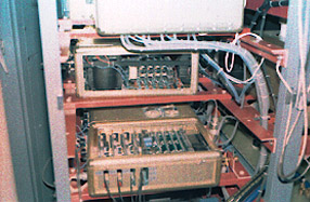
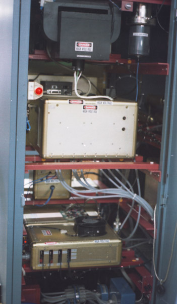
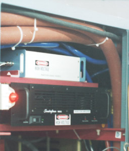
| All the boxes in this bay float at 50 KV. |
 |
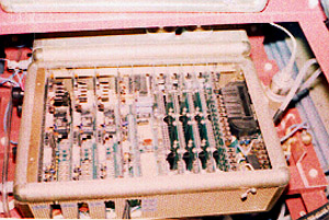
| The form-factor for the grid modulator was done by Daniel Goluzek and Ken Lillis. They beefed up and repackaged our first-generation solid-state modulator. version of the last generation modulator. I reverted many features back to earlier rev. levels but kept the shell and tube chassis. Ken's non-coincident pulse detect circuit stayed in. Wendel did the regulators. |
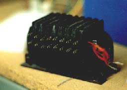
| The tube chassis for the grid box sports six ea. 350 Watt ceramic tetrodes, filament transformers, and screen supplies--quite sleek. Good work Ken and Daniel! |
 |
 |
| Daniel went with a switching mode supply to power his floating switchdecks. It was too noisy for me. So I prototyped a 60 Hz transformer to do the job. |
 |
| Request for quote denied: nobody would touch this. Each engineer hit this brick wall and did a signature dodge. I picked this core out from my stockpile at home, built the first one, and made a winding chart. Then an RFP brought back the winning bid of $130 ea. (qty: 19). |
| SoundCrafstmen amp's are beefy. Used here in the bridge mode, it puts out 340 V peak to peak. It blew the stock 20 Amp. circuit breaker whenever output exceeded 15 Amp's average at 120 VAC. I arced it with 20 KV, 1,000 Amp's routinely. Of course I'd protected it correctly first. It takes a 50 nanosecond rise-time, 20 Amp pulse of beam current without instability. |
 |
| Rick Schaffer Did the floating scopes |
| Inductance was a concern for the cathode injection transformer secondary. Magna Stangenese met a 1 microhenry specification using a single-turn ribbon-type secondary. I load it heavily with a low inductance resistor. The resistor appears in series with the cathode-supply output. |
| Dan Burke found the SoundCraftsmen amp. |
| Heater Box 20VDC, 20A |
| 3 KV swing Grid Modulator |
| Injection Transformer for heater, grid, and cathode |
| 10,000:1 Cap. Div. |
| 3.3KV Xfmr. SSR, softstart |
| Output Panel |
| Current Viewing Xfmr's |
| IEEE 488 HPIB fiber-optic link |
| 4CW 30,000 |
| Floating Scope |
| Htr. Box |
| VCO and VCA 50 Hz to 20 KHz |
| 15 VAC X 8ea. < 50 pf. isolation: 3 KV RF |
| 115 VAC |
| Tek 40 KV HV Probe |
| Output resistor |
| pulldown |
| output |
| switch cards |
| Reg-tube chassis |
| reg-amp-IP Bds |
| pulse steering fault detect |
| 1450 W RMS |
| Anode modulator |
| Grid modulator |
| Htr box |
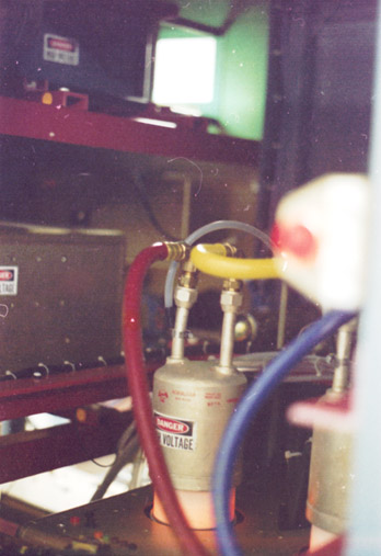
| resistor and crowbar tank |
| 120 vac |
| bias |

|
| collector regulator |