 |
| Left Over Parts Bracket (LOP) |
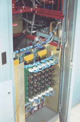
| This configuration drew the ire of a few senior engineers. The relay logic panel could have just as well connected to buttons on a front panel, and lamps, etc. The three identical boards directly behind the relay panel are each loaded with 16 computer activatible relays, and one watchdog relay. They are used in the place of front panel buttons, to operate the logic, as an operator would. I went this way because the "RC/Status readback" boards had never glitched. One look at the design clarifies why: the natural state of the board has it addressing a non-existent relay. Buttons on the control-head are programmed to activate coresponding relays here. An external computer also has control when desired. Fiber-optic coupling imunizes data-flow to noise. A broken fiber drops the watchdog relay after one second, which turns the regulated system power off. I saw one of these boards get torched with a 35KV sustained arc to the connecting harness. A technician replaced all the chips and the fiber-optic-reciever; it worked again! I was impressed. |
| My pal Jake specified a slo-blo relay board. He also found the best relays for the job. The LOP bracket typically houses the 24V supply, fiber optic transmitters and recievers, and whatever else needs a home. Line regulation and pass-tube-drop regulator boards also go in this one. |
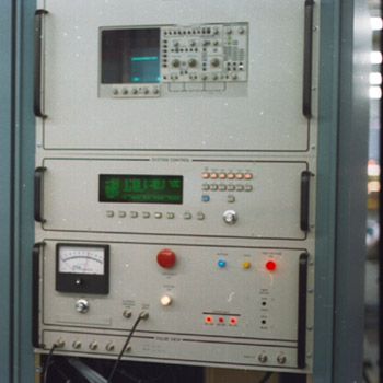 |
| Steve Warner, built our control-head from scratch: it is Intel 186 based. One tiny line in the spec. necessitated that we develop the floating oscilliscope assembly: required was a grid-voltage-view jack. But the grid modulator is referenced to the 50-KV cathode supply. Diffirential measurement was an option. But this is the hot setup. It's another area of importance. We don't skimp. A fiber-optic-link brings the data down to ground level from an IEEE-488 HPIB port, on an oscilliscope so equipped. Having the oscilliscope also facilitates the setting of injected frequencies and amplitudes (the system has an injection option for most electrodes, adjustable amplitude, from 50 HZ to 20 KHZ). Cathode and collector voltage viewing capacitive-dividers facilitate this for these at ground level. Internally terminated current transformers provide for ground referenced current viewing of all electrodes. Floatable cal. loop is provided. |
| We naturally provide an analog trip-point meter for body current. That's the reading a tube guy diddles downward. Too much intercept current within the "bore" can melt the internal RF structure. This proceeds in phases and with a thermal-runaway characteristic, ending in catastrophic loss. Heat ruins the magnets used for focusing the beam. To defocus causes heating under the magnets, which makes them worse. If you catch it before internal damage is done, external magnet re-stacking might fix it. Computers tend to bury important settings. Analog body current metering featuring settable "red-line" overload protection aims to nurture an intuitive sense of stewardship. The tube for this system cost about $150,000 at the time we built these units. Bright phase indicator LEDs are transformer coupled from primary power. The customer wanted yellow indication for fault, blue indication for bypassed fault, and red for high-voltage on. Older units had a multitude of such colored lamps, for all the individual modules. We did fine with just the three because the control head tells you what is happening. |

|