JAL Computing
![]()
![]()
![]()
![]()
![]()
|
|
|
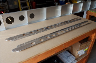
Building the RV12 WingWhere we start the great adventure. Preparing the Attach AnglesThe angles need to be prepared. Leave on the plastic sheeting and remove the "hatched" material as instructed using a medium wheel on a bench grinder. Then remove the plastic and radius the corners of the angles. You can use the corners of the factory attach angles on the spar as a rough guide, but be a bit more aggressive on the thinner attach angles. Once you have the corners radiused, de-burr the edges with the swivel de-burr tool or speed de-burr tool. Then use the ScotchBrite wheel on a bench grinder to de-burr (radius) the edges and de-burr the corners. I did a final pass over the edges and corners with a ScotchBrite wheel and ScotchBrite pad until smooth. Wing Kit picked up from the factory on 8/11/2008. Section 13 Spar Assembly Completed 9/1/2008.
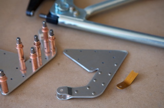
Machine Micro Countersinking
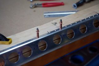
The plans call for machine countersinking many of the flange holes in the stub spar assembly. Be sure to use the 1/8" (#30) 120 degree countersink and practice on scrap aluminum. Once the depth has been properly set you can countersink the flanges. Hold the stop against the aluminum with one hand, to keep it from spinning, while drilling with the other hand. One author recommends using more pressure and a lower drill speed than for drilling. Go slowly and use the proper pressure to avoid drill "chatter." The countersink can also chatter if the pilot reaches the back of the spar. Some authors recommend placing a shim behind the spar to keep the countersink post from wobbling. A drop of tooling oil may extend the life of the bit. I drilled holes in a 2X4 to match the spacing in the sub spar assembly. I enlarged one hole and marked it on the 2X4. I then cleco-ed the spar to the 2X4 and machine countersunk the hole over the mark in the 2X4. Note the scrap aluminum with a 1/4" hole and a dimple used for final inspection of the countersink. I needed to create a few "sets" of holes to accommodate the variable spacing.
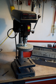
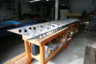
Stub Spar AssemblyI mounted a second 6 inch ScotchBrite wheel on a drill press to de-bur the straight edges of the stub spar assembly. The remaining edges and lightening holes were prepared with hand tools and a 1 inch ScotchBrite wheel on a die grinder. Be careful with the die grinder which is harder to control than the 6 inch wheel on a bench grinder.
Countersink both sides of the three inboard #40 openings and squeeze the flush rivets until both the machine heads and shop heads (see below) are flush.
Stub Spar Assemblies completed 9/14/2008
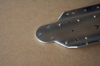
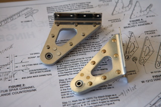
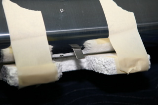
W1216 Hinge AssemblyI used the Avery solid rivet shop head rivet gauge to help set the hand squeezer and confirm the proper configuration of the 1/8 inch shop heads in the hinge assembly. IMHO, the AN470AN 4-4 is a bit short for this application. If you squeeze the rivet so that the shop head diameter is greater than 0.163 inches and slightly less than the recommended 1.5 times the rivet diameter, the shop head depth should be within specs of 0.05 to 0.07 inches.
W1216 Hinge Assemblies completed 9/18/2008
W1212 Hinge AssemblyI countersunk both sides for the AN426 rivets for a flush machine head, but I did not get an absolutely flush shop head on the two AN426 rivets using a hand squeezer. I ended up filing the shop heads a bit. I decided to prime these parts and the hinge assemblies since they are more exposed.
W1212 Hinge Assemblies completed 9/19/2008
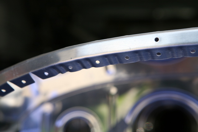
De-burring RibsThe rib edges and lightening holes are sheared with a series of sequential punches using a computerized tool. These edges need to be de burred to remove sharp surfaces that can "cause stress concentrations which will greatly increase the risk of locale failure..." For instance, sharp surfaces on the ribs may cut into the overlying sheet metal over time. If you have lots of time, this can be done with a file, followed by sanding with a ScotchBrite pad. The RV instructions suggest using a de-burring tool followed by a pass or two over a ScotchBrite wheel mounted on a bench grinder as "the best and quickest method." IMHO, the scalloped edges of the ribs do not lend themselves easily to this technique. I used a de-burring tool followed by a pass or two over a one inch ScotchBrite wheel mounted on high speed (20,000 rpm) hand grinder.
Fluting RibsYou will also need to flute the ribs. In the manufacturing process the ribs become slightly bowed. You can tell this by laying the rib on a flat table. The ribs should be straightened by fluting or creasing the flanges with a special set of fluting pliers. If you overdo it, you can try to straighten the flanges using a seamer. Consider making the primary indentation away from the side that will interface with the wing skin so that the flutes do not displace the skins away from the rivet hole.
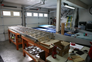
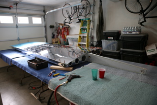
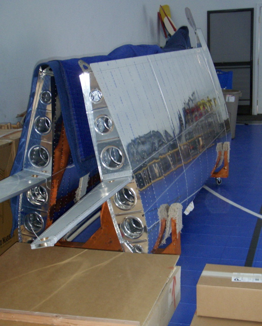
First Inspection, Skinning the Wings and Brownie PointsI had Butch from our local airport inspect the wing before I started to skin the wing. I highly recommend getting a second pair of eyes on the plane at this point. It will improve both your plane and your confidence to have an experienced builder look at your work. Butch suggested that I spend just as much effort de-burring the edges of the wing skins, as I had spent preparing the attach angles and ribs. I decided to rivet the skin to the spar first, taking care to insert rivets into the most difficult holes where the skin, spar and main ribs meet, before I started any actual riveting. I then riveted from the spar outward treating each rib as a unit of work. I placed the wing on four large "luncheon" folding tables covered with moving pads. If you have a cat that gets in the garage, definitely consider covering the wing with a set of moving pads at night. I also used the moving pads to protect the surface of the wing when riveting. The wife is starting to complain about having to park her displaced car outside in the cold, so if you plan on building an RV in your garage, I highly recommend building up a LOT of brownie points:) Here are some pictures of the main ribs on the left wing and the skin being applied to the right wing.
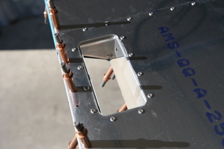
You will need to drill out an opening in the bottom of the wings for the tie downs. I started with a small unibit drill that fit into the #30 hole and then finished the hole with a medium unibit drill.
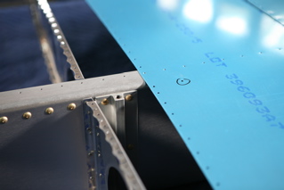
Riveting the Middle Top SkinI inserted the middle top skin before I riveted in the outboard top skin. Here is a picture of the middle top skin prepared for riveting.
I ran some 40# fishing line with a loop on each end through the wing fairleads as instructed Here is the picture of the outboard end of the right wing showing the fishing line.
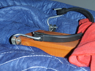
Wing Handle, Hinges and Complete Wing
The right handle being riveted in place.
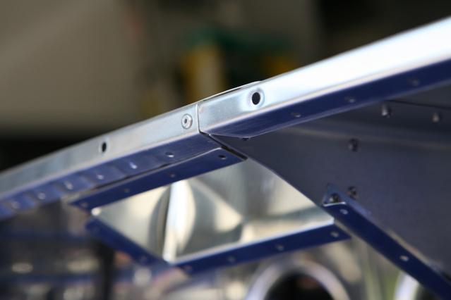
The hinge after being riveted in place.
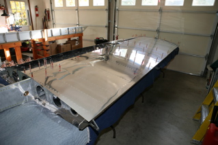
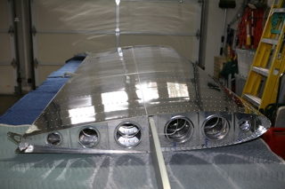
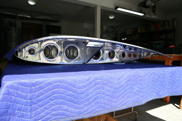
Here is the completed right wing (upside down). It feels great! Thanks VANs! Right Wing Completed 12.19.2008
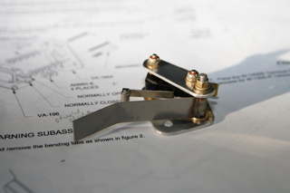
Left WingNow that my replacement parts have arrived, I am working to complete the left wing. Here is the stall warning assembly ready to be installed on the nose rib. The width of the supplied AN960-4 washers are variable. By MilSpecs, five AN960-4 washers should provide (5 X 0.032 inch) 0.160 inches of clearance between the VA-195A plate and the micro switch. My shipment of AN960-4 washers had a width of 0.023 inches, requiring 7 washers to achieve the recommended spacing (7 X 0.023 or 0.161 inches).
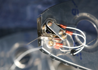
Consider purchasing #8 and #4 machine countersink cutters (100 degrees) and numbered drills (#19 and #31) specific for the #8 and #4 countersink screws. Note that the wire terminals used in aviation are "double crimp." I used a ratchet style tool to place a hard crimp on the wire and a non ratcheting crimp tool to place a soft crimp on the insulation. Here is the stall warning switch installed on the nose rib.
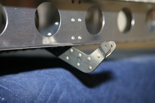
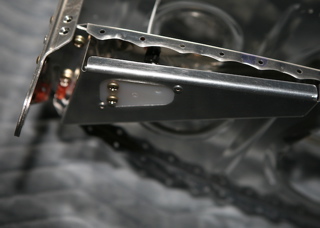
The bracket is installed inboard on both wings. I was short some locking nuts.
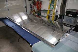
Here is a view of the outboard edge of the left wing.
I padded the stall warning switch to protect it from damage.
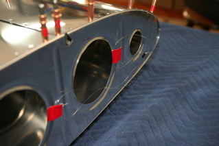
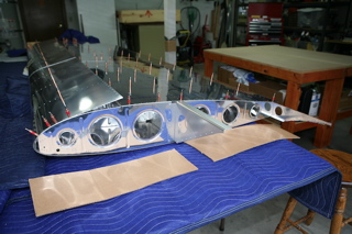
Wing Tip CloseoutHere is a view of the left wing tip before closeout.
To curve the edge of the forward wing tip rib, consider two aggressive flutes as pictured below.
Some hand filing may improve the fit between the overlapping forward and aft wing tip ribs.
Consider deferring the bending of the 116 degree forward tab on the closeout until after a dry fitting of the closeout on the wing. This will allow a custom bending of the 116 degree forward tab parallel to the existing wing. Finally, I clecoed the close out to the left wing before turning over the left wing. See FAQs for hints about the wing construction. Here are both wings in the wing stand. Note the safety device!
Have fun!
|
Send mail to [email protected]
with questions or comments about this web site. Copyright © 2001, 2002, 2003,
2004, 2005, 2006, 2007, 2008, 2009 ©
|