A healthy commutator has a dark color, usually approaching a deep chocolate brown. Occasionally, however, a commutator will become dirty and very black. It then may be cleaned by washing and wiping with gasoline, after which it should be polished with No. 00 sandpaper. Do not use emery paper or emery cloth, as this will short circuit the communtator. After sandpapering, brush or blow all loose sand out of the generator.
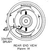
Model 206 and 212 generators are adjusted at the factory for proper output, and the setting of the control brush should not be changed unless it is absolutely necessary. In case the generator is taken apart or the brush adjustment is disturbed for any other reason, an approximate adjustment can be made by moving the control brush so that two full commutator bars are visible between the toe of the control brush and the toe of the insulated main brush. See Figure 16.
When so adjusted, the generator should perform according to the table below, when the machine is cold and when charging at 7 to 8 volts, as on a half charged battery.
| AMPERES | AMPERES | |
| R.P.M. | Model 206 six volt | Model 212 twelve volt |
| 375 | 1 | 1/2 |
| 500 | 6 | 3 |
| 700 | 14 | 7 |
| 900 | 20 | 10 |
| 1100 | 24 | 12 |
| 1300 | 26 | 13 |
The above figures are for the cold generator. As it runs and warms up, the output will become less. The Model 212 generator will deliver about 11 amperes at 14 volts, maximum output when the generator is warm.
Do not adjust the control brush for outputs higher than given above. To do so will overload the generator so that it will burn out and severe sparking of the brushes will result.
The collector assembly consists of two collector arms in the main frame and two stationary post contacts on the main stem. They require very little attention. If the sliding contacts become rough or pitted, they can be polished with No. 00 sandpaper. Do not grease or oil the collector ring, as this will only collect dust, which will increase the wear.
The condenser mounted under the main frame by-passes radio noise from the generator to the ground. It should make no trouble unless hit by lightning.
The relay and ammeter are mounted on the instrument panel. The relay serves as a check valve between the battery and the generator. It closes the circuit when the generator develops enough voltage to charge the batteries and opens it when the generator output falls to where the batteries are no longer charged.
The ammeter simply tells when the generator is delivering current to the battery. It will not show charge until the relay closes and its reading changes with the speed of the generator. These ammeters show only approximate readings and should not be relied on too strongly when checking the output of the generator.
Many cases of trouble can be located without much difficulty if proper tests are made. The suggestions below , if followed, will often help to clear minor difficulties. Usually, when the cause of the trouble is located, the repair is quite simple. If, however, the trouble is of a serious nature or is not easily repaired locally, it is advisable to write the factory, answering the questions given on page 18 of this manual. If we cannot help you by letter, we will authorize you to return the damaged parts to the factory.
| << Previous Page | Return to Home Page | Next Page >> |