| HOME | NEWS | PHOTO GALLERY | COMPUTER PLUS | COOKING PLUS | ABOUT THE SITE | CONTACT |
| GRIDS Tutorial |
|
Grids Introduction Grids is an amazing piece of freeware that enables you to draw circuit diagrams, schematics, flow charts , and many more similar drawings very easily.If the required symbols are not available you can create your own.
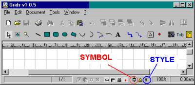
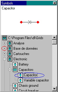
To draw a diagram using existing symbols After you start grids click on File ---> New. (or Ctrl + N ) or click on the symbol for new on the tool bar. You will see a display as shown in the Figure 1. There are a few symbols on the bottom of the screen , two of which have been labelled in the Figure 1. One denotes the symbols toolbar and the other the style toolbar. Click on the symbol denoting the symbol toolbar. You will see a list of different types of symbol libraries. Click on the plus sign until it changes to minus and you can see the symbol list. For example the Electronic symbol library consists of the folders capacitors , diodes ,inductors, resistors, transistors and the symbols for battery, chassis ground etc. Clicking on the plus sign next to capacitors reveals two symbols capacitor and variable capacitor.
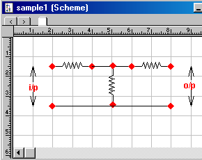
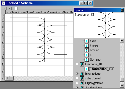
Clicking on capacitor displays the corresponding symbol in the symbol toolbar. We can use the use the symbol in our drawing by dragging the name capacitor from the symbol toolbar to
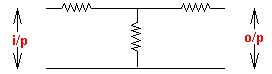
our diagram. Figure 3 shows a simple circuit diagram in grids window and Figure 4 shows the diagram as it will be printed.
You can change the style of the various objects ( lines, rectangles, circles, arcs etc) by selecting them after drawing them and then changing their style in the style bar. In the case of text first select draw the text box and then set the properties in the style bar. Creating New Libraries and Symbols If the symbols that we require are not present in Grids we can create special symbols for our use. For example there are no symbols for Process Control
Instrumentation. Also symbols to represent various types of transformers are also not present. If we wish to use such symbols in our diagrams we will have to create the necessary libraries and
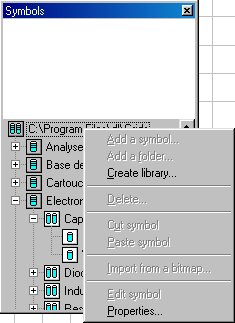
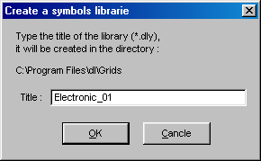
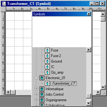
symbols. In the example that follows we will learn how to create the symbol for a step down transformer. Creating New Libraries If the symbol library toolbar is not displayed display it by clicking on the appropriate button at the bottom of the screen. Then right click on the root of the symbol library in the toolbar (See Figure 5). If you have installed in the default path it will be C:\Program Files\dl\Grids as in Figure 5. From the popup menu that appears select Create Library. Then type the name for your new library and click OK. Your library has been created. Here we have created a new library Electronic_01 to create some symbols not included in Grids.
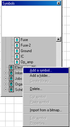
Creating New Symbols I am going to create the symbol of a step down centre tapped transformer that is commonly used in rectifier circuits as an example of a new symbol. Next right click on Electronic_01 and from the popup menu that appears select Add a Symbol (See Figure 7).
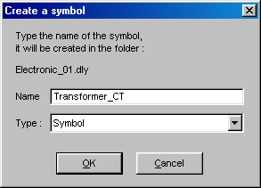
Then type the name for your new symbol (Here we have used the name Transformer_CT to denote transformer with centre tap) and click OK. The name Transformer_CT will appear under Electronic_01 in the symbol library structure as seen in Figure 9.
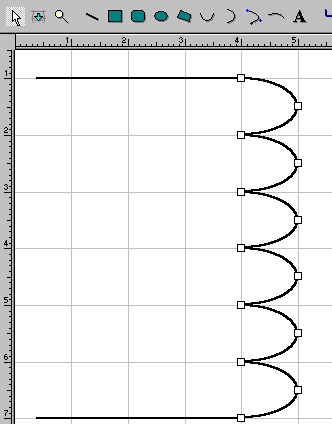
Then click on Transformer_CT and you will see a blank page with the heading as shown in Figure 9. Click on the zoom tool and zoom the sheet until it is maximum. Using the line tool draw a horizontal line on top starting from the left side. Then use the vertical semi oval tool and draw the primary coil by drawing about 6 semicircles (See Figure 10).
Click on the arrow key and select all the semicirles by keeping the shift key pressed and clicking on each semicirle. Then copy and paste. Once it is pasted if you move your mouse over the pasted object you will notice the cursor changes into a 4 directional arrow . Drag the object to a location that you require. Then click on the vertical symmetry button and the secondary coil is drawn. Draw the core (two vertical lines in centre) using the line tool, and then place the coil in position by
dragging it . You can reduce the length of the secondary coil by reducing one semicircle at the top and bottom . Select the top semicircle by using the arrow tool and press the del key on the keyboard. Similarly delete the bottom semicircle. Draw three lines ,one on top ,one at bottom and one at center (Centre Tap). You can now save the symbol by clicking on the save button.Figure 11 shows the completed symbol. |