|
|
|
Iare IT 2005-2009 |
|
|
|
Iare IT 2005-2009 New User? Sign Up
Iare IT 2005-2009 Not a member yet? JOIN NOW
click here or check the college/class section
Unit 1 read online Download now
Unit 2 read online Download now
Unit 3 read online Download now
Unit 4 read online Download now (still not available)
|
|
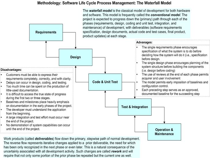
Basics of Software Life Cycle and Waterfall Model 2.1 Life cycle model A software life cycle model (also called process model) is a descriptive and diagrammatic representation of the software life cycle. A life cycle model represents all the activities required to make a software product transit through its life cycle phases. It also captures the order in which these activities are to be undertaken. In other words, a life cycle model maps the different activities performed on a software product from its inception to retirement. Different life cycle models may map the basic development activities to phases in different ways. Thus, no matter which life cycle model is followed, the basic activities are included in all life cycle models though the activities may be carried out in different orders in different life cycle models. During any life cycle phase, more than one activity may also be carried out. For example, the design phase might consist of the structured analysis activity followed by the structured design activity. The need for a software life cycle model The development team must identify a suitable life cycle model for the particular project and then adhere to it. Without using of a particular life cycle model the development of a software product would not be in a systematic and disciplined manner. When a software product is being developed by a team there must be a clear understanding among team members about when and what to do. Otherwise it would lead to chaos and project failure. This problem can be illustrated by using an example. Suppose a software development problem is divided into several parts and the parts are assigned to the team members. From then on, suppose the team members are allowed the freedom to develop the parts assigned to them in whatever way they like. It is possible that one member might start writing the code for his part, another might decide to prepare the test documents first, and some other engineer might begin with the design phase of the parts assigned to him. This would be one of the perfect recipes for project failure. A software life cycle model defines entry and exit criteria for every phase. A phase can start only if its phase-entry criteria have been satisfied. So without software life cycle model the entry and exit criteria for a phase cannot be recognized. Without software life cycle models (such as classical waterfall model, iterative waterfall model, prototyping model, evolutionary model, spiral model etc.) it becomes difficult for software project managers to monitor the progress of the project. Different software life cycle models Many life cycle models have been proposed so far. Each of them has some advantages as well as some disadvantages. A few important and commonly used life cycle models are as follows: Classical Waterfall Model ,Iterative Waterfall Model , Prototyping Model, Evolutionary Model Spiral Model Different phases of the classical waterfall model The classical waterfall model is intuitively the most obvious way to develop software. Though the classical waterfall model is elegant and intuitively obvious, it is not a practical model in the sense that it can not be used in actual software development projects. Thus, this model can be considered to be a theoretical way of developing software. But all other life cycle models are essentially derived from the classical waterfall model. So, in order to be able to appreciate other life cycle models it is necessary to learn the classical waterfall model. Classical waterfall model divides the life cycle into the following phases as Feasibility Study Requirements Analysis and Specification Design Coding and Unit Testing
Integration and System Testing
Activities in each phase of the life cycle • Activities undertaken during feasibility study: - The main aim of feasibility study is to determine whether it would be financially and technically feasible to develop the product. At first project managers or team leaders try to have a rough understanding of what is required to be done by visiting the client side. They study different input data to the system and output data to be produced by the system. They study what kind of processing is needed to be done on these data and they look at the various constraints on the behavior of the system. After they have an overall understanding of the problem they investigate the different solutions that are possible. Then they examine each of the solutions in terms of what kind of resources required, what would be the cost of development and what would be the development time for each solution. Based on this analysis they pick the best solution and determine whether the solution is feasible financially and technically. They check whether the customer budget would meet the cost of the product and whether they have sufficient technical expertise in the area of development. The following is an example of a feasibility study undertaken by an organization. It is intended to give you a feel of the activities and issues involved in the feasibility study phase of a typical software project. Case Study A mining company named Galaxy Mining Company Ltd. (GMC) has mines located at various places in India. It has about fifty different mine sites spread across eight states. The company employs a large number of mines at each mine site. Mining being a risky profession, the company intends to operate a special provident fund, which would exist in addition to the standard provident fund that the miners already enjoy. The main objective of having the special provident fund (SPF) would be quickly distribute some compensation before the standard provident amount is paid. According to this scheme, each mine site would deduct SPF installments from each miner every month and deposit the same with the CSPFC (Central Special Provident Fund Commissioner). The CSPFC will maintain all details regarding the SPF installments collected from the miners. GMC employed a reputed software vendor Adventure Software Inc. to undertake the task of developing the software for automating the maintenance of SPF records of all employees. GMC realized that besides saving manpower on bookkeeping work, the software would help in speedy settlement of claim cases. GMC indicated that the amount it can afford for this software to be developed and installed is Rs. 1 million. Adventure Software Inc. deputed their project manager to carry out the feasibility study. The project manager discussed the matter with the top managers of GMC to get an overview of the project. He also discussed the issues involved with the several field PF officers at various mine sites to determine the exact details of the project. The project manager identified two broad approaches to solve the problem. One was to have a central database which could be accessed and updated via a satellite connection to various mine sites. The other approach was to have local databases at each mine site and to update the central database periodically through a dial-up connection. These periodic updates could be done on a daily or hourly basis depending on the delay acceptable to GMC in invoking various functions of the software. The project manager found that the second approach was very affordable and more fault-tolerant as the local mine sites could still operate even when the communication link to the central database temporarily failed. The project manager quickly analyzed the database functionalities required, the user-interface issues, and the software handling communication with the mine sites. He arrived at a cost to develop from the analysis. He found that the solution involving maintenance of local databases at the mine sites and periodic updating of a central database was financially and technically feasible. The project manager discussed his solution with the GMC management and found that the solution was acceptable to them as well. • Activities undertaken during requireme nts analysis and specification: - The aim of the requirements analysis and specification phase is to understand the exact requirements of the customer and to document them properly. This phase consists of two distinct activities, namely Requirements gathering and analysis, and Requirements specification The goal of the requirements gathering activity is to collect all relevant information from the customer regarding the product to be developed. This is done to clearly understand the customer requirements so that incompleteness and inconsistencies are removed. The requirements analysis activity is begun by collecting all relevant data regarding the product to be developed from the users of the product and from the customer through interviews and discussions. For example, to perform the requirements analysis of a business accounting software required by an organization, the analyst might interview all the accountants of the organization to ascertain their requirements. The data collected from such a group of users usually contain several contradictions and ambiguities, since each user typically has only a partial and incomplete view of the system. Therefore it is necessary to identify all ambiguities and contradictions in the requirements and resolve them through further discussions with the customer. After all ambiguities, inconsistencies, and incompleteness have been resolved and all the requirements properly understood, the requirements specification activity can start. During this activity, the user requirements are systematically organized into a Software Requirements Specification (SRS) document. The customer requirements identified during the requirements gathering and analysis activity are organized into a SRS document. The important components of this document are Functional requirements, the nonfunctional requirements, and the goals of implementation. • Activities undertaken during design: - The goal of the design phase is to transform the requirements specified in the SRS document into a structure that is suitable for implementation in some programming language. In technical terms, during the design phase the software architecture is derived from the SRS document. Two distinctly different approaches are available: the traditional design approach and the object-oriented design approach. Traditional design approach Traditional design consists of two different activities; first a structured analysis of the requirements specification is carried out where the detailed structure of the problem is examined. This is followed by a structured design activity. During structured design, the results of structured analysis are transformed into the software design. Object-oriented design approach In this technique, various objects that occur in the problem domain and the solution domain are first identified, and the different relationships that exist among these objects are identified. The object structure is further refined to obtain the detailed design. • Activities undertaken during coding and unit testing:- The purpose of the coding and unit testing phase (sometimes called the implementation phase) of software development is to translate the software design into source code. Each component of the design is implemented as a program module. The end-product of this phase is a set of program modules that have been individually tested. During this phase, each module is unit tested to determine the correct working of all the individual modules. It involves testing each module in isolation as this is the most efficient way to debug the errors identified at this stage. • Activities undertaken during integration and system testing: - Integration of different modules is undertaken once they have been coded and unit tested. During the integration and system testing phase, the modules are integrated in a planned manner. The different modules making up a software product are almost never integrated in one shot. Integration is normally carried out incrementally over a number of steps.During each integration step, the partially integrated system is tested and.a set of previously planned modules are added to it. Finally, when all the modules have been successfully integrated and tested, system testing is carried out. The goal of system testing is to ensure that the developed system conforms to its requirements laid out in the SRS document. System testing usually consists of three different kinds of testing activities: – testing: It is the system testing performed by the development team. It is the system testing performed by a friendly set of customers. acceptance testing: It is the system testing performed by the customer himself after the product delivery to determine whether to accept or reject the delivered product. System testing is normally carried out in a planned manner according to the system test plan document. The system test plan identifies all testing-related activities that must be performed, specifies the schedule of testing, and allocates resources. It also lists all the test cases and the expected outputs for each test case. • Activities undertaken during maintenance: - Maintenance of a typical software product requires much more than the effort necessary to develop the product itself. Many studies carried out in the past confirm this and indicate that the relative effort of development of a typical software product to its maintenance effort is roughly in the 40:60 ratio. Maintenance involves performing any one or more of the following three kinds of activities: Correcting errors that were not discovered during the product development phase. This is called corrective maintenance. Improving the implementation of the system, and enhancing the functionalities of the system according to the customer’s requirements. This is called perfective maintenance. Porting the software to work in a new environment. For example, porting may be required to get the software to work on a new computer platform or with a new operating system. This is called adaptive maintenance. Shortcomings of the classical waterfall model The classical waterfall model is an idealistic one since it assumes that no development error is ever committed by the engineers during any of the life cycle phases. However, in practical development environments, the engineers do commit a large number of errors in almost every phase of the life cycle. The source of the defects can be many: oversight, wrong assumptions, use of inappropriate technology, communication gap among the project engineers, etc. These defects usually get detected much later in the life cycle. For example, a design defect might go unnoticed till we reach the coding or testing phase. Once a defect is detected, the engineers need to go back to the phase where the defect had occurred and redo some of the work done during that phase and the subsequent phases to correct the defect and its effect on the later phases. Therefore, in any practical software development work, it is not possible to strictly follow the classical waterfall model. Phase-entry and phase-exit criteria of each phase At the starting of the feasibility study, project managers or team leaders try to understand what is the actual problem by visiting the client side. At the end of that phase they pick the best solution and determine whether the solution is feasible financially and technically. At the starting of requirements analysis and specification phase the required data is collected. After that requirement specification is carried out. Finally, SRS document is produced. At the starting of design phase, context diagram and different levels of DFDs are produced according to the SRS document. At the end of this phase module structure (structure chart) is produced. During the coding phase each module (independently compilation unit) of the design is coded. Then each module is tested independently as a stand-alone unit and debugged separately. After this each module is documented individually. The end product of the implementation phase is a set of program modules that have been tested individually but not tested together. After the implementation phase, different modules which have been tested individually are integrated in a planned manner. After all the modules have been successfully integrated and tested, system testing is carried out. Software maintenance denotes any changes made to a software product after it has been delivered to the customer. Maintenance is inevitable for almost any kind of product. However, most products need maintenance due to the wear and tear caused by use.
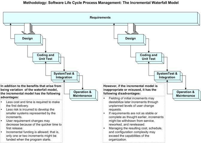
2.2 Incremental Process model
Incremental development advantages
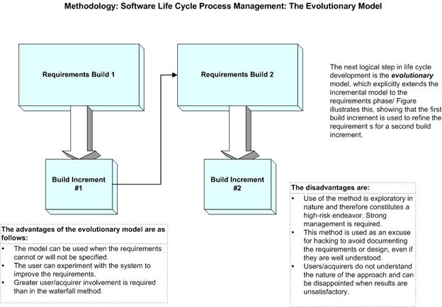
2.3 Evolutionary development
·
Objective is to work with customers and to evolve a final system from an
initial outline specification. Should start with well-understood
requirements and add new features as proposed by the customer. 2.3.1 Prototyping Life Cycle Models Prototype : A prototype is a toy implementation of the system. A prototype usually exhibits limited functional capabilities, low reliability, and inefficient performance compared to the actual software. A prototype is usually built using several shortcuts. The shortcuts might involve using inefficient, inaccurate, or dummy functions. The shortcut implementation of a function, for example, may produce the desired results by using a table look-up instead of performing the actual computations. A prototype usually turns out to be a very crude version of the actual system. Need for a prototype in software development There are several uses of a prototype. An important purpose is to illustrate the input data formats, messages, reports, and the interactive dialogues to the customer. This is a valuable mechanism for gaining better understanding of the customer’s needs: • how the screens might look like • how the user interface would behave • how the system would produce outputs This is something similar to what the architectural designers of a building do; they show a prototype of the building to their customer. The customer can evaluate whether he likes it or not and the changes that he would need in the actual product. A similar thing happens in the case of a software product and its prototyping model. Another reason for developing a prototype is that it is impossible to get the perfect product in the first attempt. Many researchers and engineers advocate that if you want to develop a good product you must plan to throw away the first version. The experience gained in developing the prototype can be used to develop the final product. A prototyping model can be used when technical solutions are unclear to the development team. A developed prototype can help engineers to critically examine the technical issues associated with the product development. Often, major design decisions depend on issues like the response time of a hardware controller, or the efficiency of a sorting algorithm, etc. In such circumstances, a prototype may be the best or the only way to resolve the technical issues. Examples for prototype model Example 1: User requirements are not complete In any application software like billing in a retail shop, accounting in a firm, etc the users of the software are not clear about the different functionalities required. Once they are provided with the prototype implementation, they can try to use it and find out the missing functionalities. Example 2: Technical issues are not clear Suppose a project involves writing a compiler and the development team has never written a compiler. In such a case, the team can consider a simple language, try to build a compiler in order to check the issues that arise in the process and resolve them. After successfully building a small compiler (prototype), they would extend it to one that supports a complete language. 2.3.2 Spiral model The Spiral model of software development is shown in fig. 2.2. The diagrammatic representation of this model appears like a spiral with many loops. The exact number of loops in the spiral is not fixed. Each loop of the spiral represents a phase of the software process. For example, the innermost loop might be concerned with feasibility study. The next loop with requirements specification, the next one with design, and so on. Each phase in this model is split into four sectors (or quadrants) as shown in fig. 2.2. The following activities are carried out during each phase of a spiral model. First quadrant (Objective Setting) • During the first quadrant, it is needed to identify the objectives of the phase. • Examine the risks associated with these objectives. - Second Quadrant (Risk Assessment and Reduction) • A detailed analysis is carried out for each identified project risk. • Steps are taken to reduce the risks. For example, if there is a risk that the requirements are inappropriate, a prototype system may be developed. - Third Quadrant (Development and Validation) • Develop and validate the next level of the product after resolving the identified risks. - Fourth Quadrant (Review and Planning) • Review the results achieved so far with the customer and plan the next iteration around the spiral. • Progressively more complete version of the software gets built with each iteration around the spiral. Circumstances to use spiral model The spiral model is called a meta model since it encompasses all other life cycle models. Risk handling is inherently built into this model. The spiral model is suitable for development of technically challenging software products that are prone to several kinds of risks. However, this model is much more complex than the other models – this is probably a factor deterring its use in ordinary projects.
Comparison of different life-cycle models The classical waterfall model can be considered as the basic model and all other life cycle models as embellishments of this model. However, the classical waterfall model can not be used in practical development projects, since this model supports no mechanism to handle the errors committed during any of the phases. This problem is overcome in the iterative waterfall model. The iterative waterfall model is probably the most widely used software development model evolved so far. This model is simple to understand and use. However, this model is suitable only for well-understood problems; it is not suitable for very large projects and for projects that are subject to many risks. The prototyping model is suitable for projects for which either the user Requirements or the underlying technical aspects are not well understood. This model is especially popular for development of the user-interface part of the projects. The evolutionary approach is suitable for large problems which can be decomposed into a set of modules for incremental development and delivery. This model is also widely used for object-oriented development projects. Of course, this model can only be used if the incremental delivery of the system is acceptable to the customer. The spiral model is called a meta model since it encompasses all other life cycle models. Risk handling is inherently built into this model. The spiral model is suitable for development of technically challenging software products that are prone to several kinds of risks. However, this model is much more complex than the other models – this is probably a factor deterring its use in ordinary projects. The different software life cycle models can be compared from the viewpoint of the customer. Initially, customer confidence in the development team is usually high irrespective of the development model followed. During the lengthy development process, customer confidence normally drops off, as no working product is immediately visible. Developers answer customer queries using technical slang, and delays are announced. This gives rise to customer resentment. On the other hand, an evolutionary approach lets the customer experiment with a working product much earlier than the monolithic approaches. Another important advantage of the incremental model is that it reduces the customer’s trauma of getting used to an entirely new system. The gradual introduction of the product via incremental phases provides time to the customer to adjust to the new product. Also, from the customer’s financial viewpoint, incremental development does not require a large upfront capital outlay. The customer can order the incremental versions as and when he can afford them. 2.4 The Rational Unified Process
2.5 Requirements Engineering
Requirements:
Types of requirement
2.5.1 Functional and non-functional requirements
o Statements of services the system should provide, how the system should react to particular inputs and how the system should behave in particular situations.
o constraints on the services or functions offered by the system such as timing constraints, constraints on the development process, standards, etc.
o Requirements that come from the application domain of the system and that reflect characteristics of that domain.
Ex: The LIBSYS system
o User intention - special purpose viewer for each different document type; o Developer interpretation - Provide a text viewer that shows the contents of the document.
o They should include descriptions of all facilities required.
o There should be no conflicts or contradictions in the descriptions of the system facilities.
2.5.2 Non-functional requirements
Non-functional classifications
o Requirements which specify that the delivered product must behave in a particular way e.g. execution speed, reliability, etc.
o Requirements which are a consequence of organisational policies and procedures e.g. process standards used, implementation requirements, etc.
o Requirements which arise from factors which are external to the system and its development process e.g. interoperability requirements, legislative requirements, etc.
§ Non-functional requirements examples
o The user interface for LIBSYS shall be implemented as simple HTML without frames or Java applets.
§ The system development process and deliverable documents shall conform to the process and deliverables defined in XYZCo-SP-STAN-95.
§ The system shall not disclose any personal information about customers apart from their name and reference number to the operators of the system.
o A general intention of the user such as ease of use.
o A statement using some measure that can be objectively tested.
o The system should be easy to use by experienced controllers and should be organised in such a way that user errors are minimised.
o Experienced controllers shall be able to use all the system functions after a total of two hours training. After this training, the average number of errors made by experienced users shall not exceed two per day.
o To minimise weight, the number of separate chips in the system should be minimised. o To minimise power consumption, lower power chips should be used. o However, using low power chips may mean that more chips have to be used. Which is the most critical requirement?
o Dtrain = Dcontrol + Dgradient § where Dgradient is 9.81ms2 * compensated gradient/alpha and where the values of 9.81ms2 /alpha are known for different types of train.
o Requirements are expressed in the language of the application domain; o This is often not understood by software engineers developing the system.
o Domain specialists understand the area so well that they do not think of making the domain requirements explicit. 2.6 User requirements
Problems with natural language
o Precision is difficult without making the document difficult to read.
o Functional and non-functional requirements tend to be mixed-up.
o Several different requirements may be expressed together.
2.6 Grid facilities To assist in the positioning of entities on a diagram, the user may turn on a grid in either centimetres or inches, via an option on the control panel. Initially, the grid is off. The grid may be turned on and off at any time during an editing session and can be toggled between inches and centimetres at any time. A grid option will be provided on the reduce-to-fit view but the number of grid lines shown will be reduced to avoid filling the smaller diagram with grid lines.
o Describes the concept of a financial accounting system that is to be included in LIBSYS; o However, it also includes the detail that managers can configure this system - this is unnecessary at this level.
o Conceptual functional requirement (the need for a grid); o Non-functional requirement (grid units); o Non-functional UI requirement (grid switching).
2.7 System requirements
Problems with NL specification
o The readers and writers of the requirement must interpret the same words in the same way. NL is naturally ambiguous so this is very difficult.
o The same thing may be said in a number of different ways in the specification.
o NL structures are inadequate to structure system requirements.
o Validate card; o Handle request; o Complete transaction
2
2.8 Interface specification
o Procedural interfaces; o Data structures that are exchanged; o Data representations.
· It is NOT a design document. As far as possible, it should set of WHAT the system should do rather than HOW it should do it · Users of a requirements document
3
2.9 IEEE requirements standard · Defines a generic structure for a requirements document that must be instantiated for each specific system. o Introduction. o General description. o Specific requirements. o Appendices. o Index.
· Glossary · User requirements definition · System architecture · System requirements specification · System models · System evolution · Appendices · Index Role of a system analyst The analyst starts requirements gathering and analysis activity by collecting all information from the customer which could be used to develop the requirements of the system. He then analyzes the collected information to obtain a clear and thorough understanding of the product to be developed, with a view to removing all ambiguities and inconsistencies from the initial customer perception of the problem. The following basic questions pertaining to the project should be clearly understood by the analyst in order to obtain a good grasp of the problem: • What is the problem? • Why is it important to solve the problem? • What are the possible solutions to the problem? • What exactly are the data input to the system and what exactly are the data output by the system? • What are the likely complexities that might arise while solving the problem? • If there are external software or hardware with which the developed software has to interface, then what exactly would the data interchange formats with the external system be?
to identify and resolve the various requirements problems. The most important requirements problems that the analyst has to identify and eliminate are the problems of anomalies, inconsistencies, and incompleteness. When the analyst detects any inconsistencies, anomalies or incompleteness in the gathered.requirements, he resolves them by carrying out further discussions with the end-users and the customers. Parts of a SRS document • The important parts of SRS document are:
Functional requirements:- The functional requirements part discusses the functionalities required from the system. The system is considered to perform a set of high-level functions {fi}. The functional view of the system is shown in fig. Nonfunctional requirements:- Nonfunctional requirements deal with the characteristics of the system which can not be expressed as functions - such as the maintainability of the system, portability of the system, usability of the system, etc. Nonfunctional requirements may include: # reliability issues, # accuracy of results, # human - computer interface issues, # constraints on the system implementation, etc. Goals of implementation:- The goals of implementation part documents some general suggestions regarding development. These suggestions guide trade-off among design goals. The goals of implementation section might document issues such as revisions to the system functionalities that may be required in the future, new devices to be supported in the future, reusability issues, etc. These are the items which the developers might keep in their mind during development so that the developed system may meet some aspects that are not required immediately. Identifying functional requirements from a problem description The high-level functional requirements often need to be identified either from an informal problem description document or from a conceptual understanding of the problem. Each high-level requirement characterizes a way of system usage by some user to perform some meaningful piece of work. There can be many types of users of a system and their requirements from the system may be very different. So, it is often useful to identify the different types of users who might use the system and then try to identify the requirements from each user’s perspective. Here we lis t all functions {fi} that the system performs. Each function fi as shown in fig.3.2 is considered as a transformation of a set of input data to some Correspondin g output data. Example:- Consider the case of the library system, where - F1: Search Book function Input: an author’s name Output: details of the author’s books and the location of these books in the library So the function Search Book (F1) takes the author's name and transforms it into book details. Functional requirements actually describe a set of high-level requirements, where each high-level requirement takes some data from the user and provides some data to the user as an output. Also each high-level requirement might consist of several other functions. Documenting functional requirements For documenting the functional requirements, we n eed to specify the set of functionalities supported by the system. A function can be specified by identifying the state at which the data is to be input to the system, its input data domain, the output data domain, and the type of processing to be carried on the input data to obtain the output data. Let us first try to document the withdraw-cash function of an ATM (Automated Teller Machine) system. The withdraw-cash is a high-level requirement. It has several sub-requirements corresponding to the different user interactions. These different interaction sequences capture the different scenarios. Example: - Withdraw Cash from ATM R1: withdraw cash Description: The withdraw cash function first determines the type of account that the user has and the account number from which the user wishes to withdraw cash. It checks the balance to determine whether the requested amount is available in the account. If enough balance is available, it outputs the required cash, otherwise it generates an error message. R1.1 select withdraw amount option Input: “withdraw amount” option Output: user prompted to enter the account type R1.2: select account type Input: user option Output: prompt to enter amount R1.3: get required amount Input: amount to be withdrawn in integer values greater than 100 and less than 10,000 in multiples of 100. Output: The requested cash and printed transaction statement. Processing: the amount is debited from the user’s account if sufficient balance is available, otherwise an error message displayed.
Properties of a good SRS document • The important properties of a good SRS document are the following: Concise. The SRS document should be concise and at the same time unambiguous, consistent, and complete. Verbose and irrelevant descriptions reduce readability and also increase error possibilities. Structured. It should be well-structured. A well-structured document is easy to understand and modify. In practice, the SRS document undergoes several revisions to cope up with the customer requirements. Often, the customer requirements evolve over a period of time. Therefore, in order to make the modifications to the SRS document easy, it is important to make the document well-structured. Black-box view. It should only specify what the system should do and refrain from stating how to do these. This means that the SRS document should specify the external behavior of the system and not discuss the implementation issues. The SRS document should view the system to be developed as black box, and should specify the externally visible behavior of the system. For this reason, the SRS document is also called the black-box specification of a system. Conceptual integrity. It should show conceptual integrity so that the reader c an easily understand it. Response to undesired events. It should characterize acceptable responses to undesired events. These are called system response to exceptional conditions. Verifiable. All requirements of the system as documented in the SRS document should be verifiable. This means that it should be possible to determine whether or not requirements have been met in an implementation. Problems without a SRS document • The important problems that an organization would face if it does not develop an SRS document are as follows: · Without developing the SRS document, the system would not be implemented according to customer needs. · Software developers would not know whether what they are developing is what exactly required by the customer. · Without SRS document, it will be very much difficult for the maintenance engineers to understand the functionality of the system. · It will be very much difficult for user document writers to write the users’ manuals properly without understanding the SRS document. Identifying non-functional requirements Nonfunctional requirements are the characteristics of the system which can not be expressed as functions - such as the maintainability of the system, portability of the system, usability of the system, etc. Nonfunctional requirements may include: # reliability issues, # performance issues, # human - computer interface issues, # interface with other external systems, # security and maintainability of the system, etc. Problems with an unstructured specification • It would be very much difficult to understand that document. • It would be very much difficult to modify that document. • Conceptual integrity in that document would not be shown. • The SRS document might be unambiguous and inconsistent. Decision tree A decision tree gives a graphic view of the processing logic involved in decision making and the corresponding actions taken. The edges of a decision tree represent conditions and the leaf nodes represent the actions to be performed depending on the outcome of testing the condition. Example: - Consider Library Membership Automa tion Software (LMS) where it should support the following three options: New member Renewal Cancel membership New member option- Decision: When the 'new member' option is selected, the software asks details about the member like the member's name, address, phone number etc. Action: If proper information is entered then a membership record for the member is created and a bill is printed for the annual membership charge plus the security deposit payable. Renewal option- Decision: If the 'renewal' option is chosen, the LMS asks for the member's name and his membership number to check whether he is a valid member or not. Action: If the membership is valid then membership expiry date is updated and the annual membership bill is printed, otherwise an error message is displayed. Cancel membership option- Decision: If the 'cancel membership' option is selected, then the software asks for member's name and his membership number. Action: The membership is cancelled, a cheque for the balance amount due to the member is printed and finally the membership record is deleted from the database. .Decision tree representation of the above example - The following tree (fig. 3.4) shows the graphical representation of the above example. After getting information from the user, the system makes a decision and then performs the corresponding actions.
Fig. 3.4: Decision tree for LMS Decision table A decision table is used to represent the complex processing logic in a tabular or a matrix form. The upper rows of the table specify the variables or conditions to be evaluated. The lower rows of the table specify the actions to be taken when the corresponding conditions are satisfied. A column in a table is called a rule. A rule implies that if a condition is true, then the corresponding action is to be executed. Example: - Consider the previously discussed LMS example. The following decision table (fig. 3.5) shows how to represent the LMS problem in a tabular form. Here the table is divided into two parts, the upper part shows the conditions and the lower part shows what actions are taken. Each column of the table is a rule. Fig. 3.5: Decision table for LMS condition
From the above table you can easily understand that, if the valid selection condition is false then the action taken for this condition is 'display error message'. Similarly, the actions taken for other conditions can be inferred from the table.
|
|||||||||||||||||||||||||||||||||||||||||||||||||||||||||||||||||