Building a small transmitting loop (Magnetic Loop)
Building
a small transmitting loop (Magnetic Loop)
Junk box loops are do-able certainly, but need just that bit more attention to the quality of connections if they are to be effective radiators. The essential point to remember is that the radiation resistance of a magloop is very low.
Rr is a concept rather than something real - whereas when you feed energy
into an antenna, some of it is lost as heat across the actual resistance of the
antenna, the energy that is radiated is said to have been dissipated across the
radiation resistance.
Clearly if Rr is low, then the actual resistance
must be kept very low indeed so that it does not dissipate most of the input
power as heat. Use single pieces of conductor with as few joints as possible,
and the largest diameter hollow conductor practical to minimise losses (hollow
because that saves weight and cost, and the RF only travels just below the skin
of the conductor anyway).
The calculations can be done with pen and paper, a calculator, or
increasingly with computer spreadsheets and dedicated programs. The calculations
that you need concern the diameter of the main conductor, the capacitance and
voltage rating of the tuning capacitor and the size and position of the
inductive feed loop - unless you are tapping the feeder directly onto the loop.
Efficiency and bandwidth are often revealed too.
'Q' or the measure of 'goodness' of a tuned circuit is one of the more tricky
parts of the calculation. It is best measured with the completed antenna in
place rather than calculated because it is so dependent on surroundings such as
feed point and proximity to earth.
Reg G4FGQ has written a number of loop design programs that are
freeware and available for download here, but some of the formulae used are
detailed here

For those of you who want to write your own programs,
perhaps for the smaller and older computers available there is a BASIC
listing that is easily converted to most dialects.
If you want to model the efficiency, radiation resistance, capacitor
voltages and sizes of an example magnetic loop (actually built in copper) the
following early version Lotus 123 compatible spreadsheet gives you 'ball-park'
figures that are really quite enlightening.
![]() Lotus123 Loop
calculations- click to download ( 6.5k )
Lotus123 Loop
calculations- click to download ( 6.5k )
![]() Excel97 Loop
calculations- click to download ( 28k! )
Excel97 Loop
calculations- click to download ( 28k! )
By way of example, I have an 180cm diameter loop for 80-30metres mounted about fifteen centimetres from the ground, against a brick wall - with a tree on the other side of it a mere thirty metres from the shack.
A smaller (80cm) loop covers 20-10metres and is mounted on an aluminium
stub about a metre above a flat roof which is itself much lower than the
surrounding buildings.
A have a similarly sized 80cm loop for 50MHz too, the loop is made from
narrow bore copper pipe (the sort used for central heating installations) which
bends easily - and has a 10pF variable air spaced variable capacitor that stays
on about 50.140MHz and gives a bandwidth of about +/- 60kHz which is very usable
on CW and SSB. 7pF tunes around 50Mhz and the same loop tunes down to 4m at a
capacitance of about 2 pF.
Drawn on a Psion series 3a palmtop using VECTOR by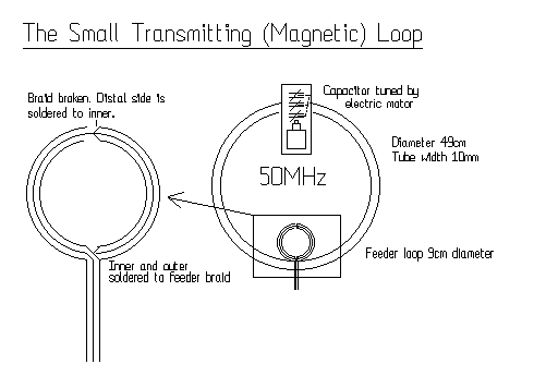 [email protected] http://www.kizzyco.com/)
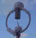
The 50MHz
loop built from narrow bore easily bent 10mm diameter copper tubing - comes in a
coil already! The loop is fastened to a 20mm diameter conduit pipe made of a
sturdy plastic. The loop is attached at the upper edge (open ends) and on its
lower edge using the same clips that normally run it along the skirting
board.
If you motorise the tuning capacitor -which is necessary if you
using the loop on anything but a spot frequency - although the bandwidth is
around a 100kHz on 6m - the control line which carries the power to the motor
should run down the midpoint of the main loop, so as to minimise eddy currents
being induced in it.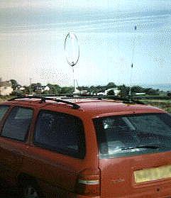
For portable or
mobile work a small aluminium stub on the car rack accepts the 20mm diameter
plastic conduit that supports the loop tuning capacitor and (at the lower end)
the coax feed loop.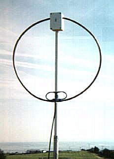
During a sunny spell I sat in the garden and worked a station in Finland with
the loop on a 12ft glass fibre mast purchased from a radio rally- seen here
co-mounted with a 2m HB9CV. The non-VHF nature of this QTH is detailed elsewhere
and this was just before 50MHz opened up for the summer....so it felt better
than it sounds..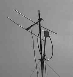
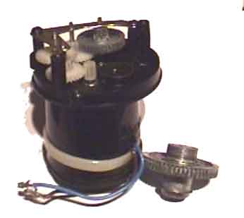
The Capco/AAA commerical loops us a BBQ spit motor and gearing together with a more conventional reduction drive. I had cause to replace on of the drive units in my 80-40m loop (perhaps because I mounted it at an angle - not vertical - Im wondering if the weight of the capacitor secured as it is at one end, caused it be harder to turn and damage first the drive gears and finally the motor.
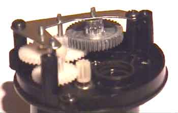
Here is a view of the disassembled gearing.
A close up of the gears
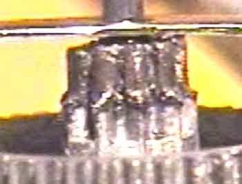
And finally a very close up of the damaged gear - notice that the teeth have been worn down uniformly all round the top of the cog - this was no sudden jam and shear failure -but wear and tear. Perhaps a lubrication issue (metal on metal?)
Amateurs have never followed rules! As high as possible and as far away from anything else as possible is a nice, but often unrealistic ideal. STLs do not like being near any conductors, because the magnetic flux is drawn to them, and induces wasteful currents that in turn produce unhelpful heat. The centre conductor that might support your loop is no exception, but so long as it is exactly central, the induced currents largely cancel out. Current will flow on the braid of the feeder if the STL (and feeder when nearby) is not symmetrical about it's capacitor for the same reason. The radiating ability of the antenna correlates with the area within the tuned loop - and since for a given length of conductor, a circle produces the biggest area AND circles can be free from lossy joints - you will less often see square STLs - although they exist.
Magnetic fields decay with distance faster than electrical fields- although at about 1/6 of a wavelength from the loop they are about equal intensity. However closer up, they are more penetrative.
STLs may therefore be more tolerant of unavoidable low level mounting than wire antennas, but by the same token, a small elevation of an STL can have a significant benefit.
Magnetic loops are fed with unbalanced co-axial feeder. Until the main
capacitor is tuned to the correct transmit frequency the antenna will not
resonate, and cannot be loaded properly. Once tuned however, the smaller loop
used to load the antenna then needs to be positioned to effect a 50 ohm (or 75?)
match with the coaxial cable being used. Any mismatch here will result in
standing waves on the coaxial cable, which in turn will radiate and reduce one
of the advantages of a magnetic loop - its narrow bandpass filter effect.
Happily, once you have a loop tuned, and then position the inductive driver
loop to get a 50ohm match, you can retune the transmitter and main loop without
having to worry about altering the loading loop - the 50ohm match works for all
resonant frequencies without further adjustment.
How to get the RF into the antenna? There are three potential ways. All the
pictures on this site show the usual method which involves terminating the
feeder co-axial cable with a loop round to the braid. This loop inductively
couples with the larger tuned loop -using air as a dialectric. It has been
customary to partially screen this loop by stripping the braid only half way
around it and joining braid to central conductor at the top of the loop- leaving
half the small loop as a single conductor to join the braid of the feeder. Some
people feel that this offers better screening from electrostatic noise, others
do it simply to make the smaller loop that bit stronger.
The second
method involves directly tapping the braid of the feeder coax to ther main loop
exactly opposite the capacitor. This is to keep the braid as electrically
neutral as possible. The centre conductor is then tapped onto the big loop to
one side of the braid connection point - adjusting for a 50 ohm match once the
main coil is resonant on the transmit frequency. It isn't that easy to get a
good connection with copper pipe however. The third method is to use a split
capacitor, and whereas the method above taps onto the inductive part of the
tuned loop, you can potentially tap onto the capacitor. It is however very
complex to do, and more of a theoretical idea, than a practical one.
Email
GW0TQM
Carl GW0TQM's
Magnetic loop page
Contributions comments and STL links welcomed.
Magloop home What? Using Building BASIC Software Links More reading and reports
Sign the
Magloop Guestbook ![]() View the
magloop Guestbook
View the
magloop Guestbook