Small Loop Control Box
The narrow bandwidth of a tuned magnetic loop means you have to have some
method of easily changing the tuning capacitor. For a 6m loop of about 1m diameter you can decide if you want FM or ssb or cw coverage, set the capacitor and you have enough bandwidth to
operate without further ado. HF loops however unless you ant a 'spot' frequency coverage need a remote means of adjustment. For portable work a long non-conductive tuning rod might do, but the real answer is to use a geared electrical motor.
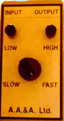
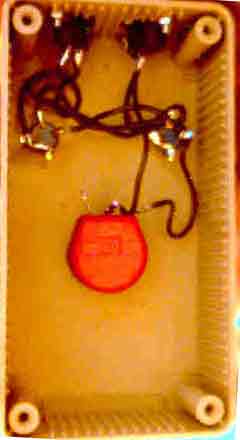
The CapCo or AA&A loop, very popular a few years ago, and my main HF antennas have a simple push switch control box.
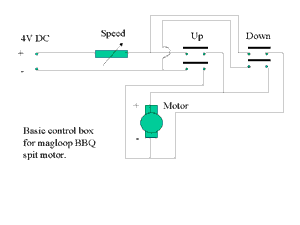
By using a DC voltage of only 3 - 4 v and a variable resistor to control the tuning speed the system effectively compensates for variations in the length of control cable- but much below 'half way' the motor stalls. A full voltage but variable pulse control box would have allowed for finer control. As it is, the up/down (or High/Low as printed on the box) are stabbed at for fine tuning. With familiarity, this is quite a quick process. The motor tends to generate some electrical noise which conveniently gets louder as the antenna reaches the tuned point! The narrowness of the antennas tuning simulating the effect of a noise bridge.
Email
GW0TQM
Carl GW0TQM's
Magnetic loop page
Contributions comments and STL links welcomed.
Magloop home What? Using Building BASIC Software Links More reading and reports
Sign the
Magloop Guestbook ![]() View the
magloop Guestbook
View the
magloop Guestbook