| Stage 7 Modification: | |||||||||||||||||||||||||||||||||||||||||||||||||
| Last Modified: 13-01-05 | |||||||||||||||||||||||||||||||||||||||||||||||||
| Turbo Upgrade | |||||||||||||||||||||||||||||||||||||||||||||||||
| The turbo upgrade comprises the replacement of the factory T25G turbo unit for the larger T28 turbo unit off the newer S15 and an after market mechanical boost controller. I purchased the turbo unit second hand as it cheaper and it bolts straight up to the existing manifold helping keep costs down for the upgrade. While trying to reduce the turbo lag that will be created with the larger turbo unit, I have also purchased a relief valve which will remain closed until boost reaches a preset level, this keeps the waste gate closed avoiding "creep" at lower boost levels. Keeping the waste gate closed longer will allow the turbo to spool faster and will help reduce power loss at low revs. Due the the motor only being 1800cc and having less low end torque than the SR20 motors the lag needs to be shorter to get up and running sooner and maintain low speed drivability. |
|||||||||||||||||||||||||||||||||||||||||||||||||
![]() |
|||||||||||||||||||||||||||||||||||||||||||||||||
![]() |
|||||||||||||||||||||||||||||||||||||||||||||||||
| Below: The dual chamber dumpipe for the T28 turbo unit, purchased 2nd hand with gaskets but never been used. | |||||||||||||||||||||||||||||||||||||||||||||||||
![]() |
|||||||||||||||||||||||||||||||||||||||||||||||||
| Above Left & Center: The T28 turbo unit from the S15. Further pipework is required for the final installation. | |||||||||||||||||||||||||||||||||||||||||||||||||
![]() |
|||||||||||||||||||||||||||||||||||||||||||||||||
| Right: The R32 skyline compressor wheel outlet finishes at 63mm dia which matches the balance of the IC pipework previously fitted | |||||||||||||||||||||||||||||||||||||||||||||||||
![]() |
|||||||||||||||||||||||||||||||||||||||||||||||||
| Left: The direct comparison between the T25 (left) and the T28 (right). | |||||||||||||||||||||||||||||||||||||||||||||||||
| After removing the factory turbo and exhaust manifold a visit to Nissan Newmarket was required to purchase all the replacement gaskets, almost $200.00 later I had enough new bits to reassemble the manifold and all turbo flanges. The removal took about 3 hours because access was tight to the underside of the car. Another hour of scraping the old gasket bits off and I was ready to rebuild. 
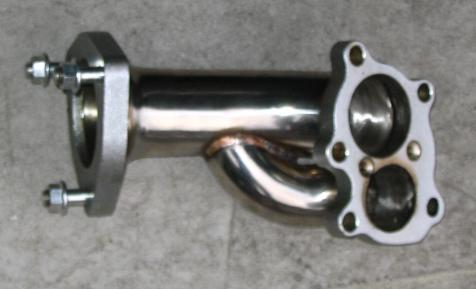
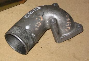
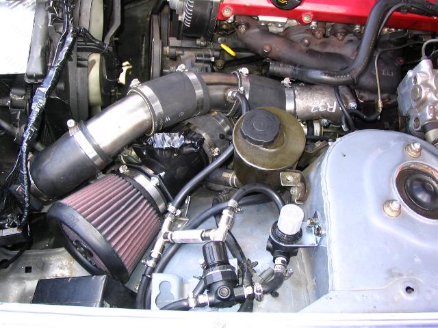
Minor mods were required to the front of the exhaust to allow it to connect to the new dump pipe, but this was completed by an exhaust fitter in about 20 minutes. The standard T25 flange was replaced with the flange off a skyline system as the dia is larger on the skyline unit and fitted the dump pipe without causing any flow restriction. 
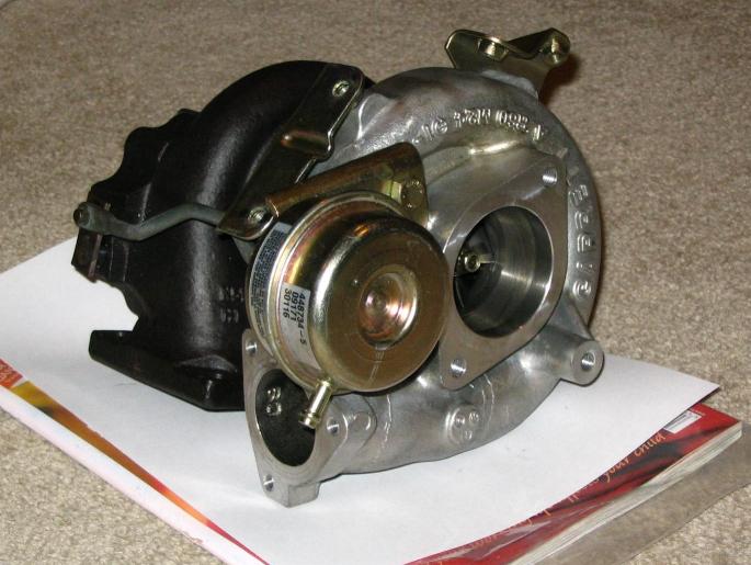
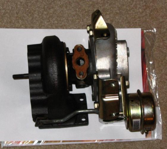
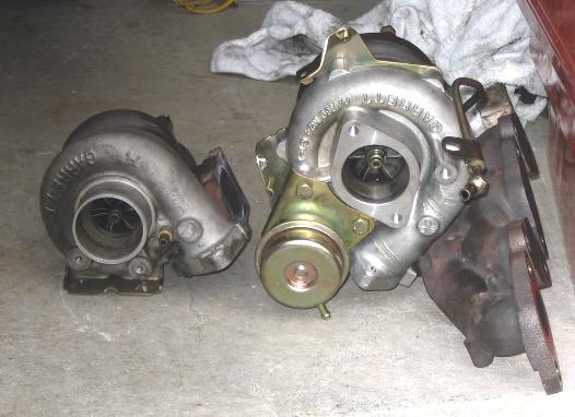
The factory T25G turbo unit is much smaller than the T28 turbo unit as seen above meaning the 2 water and 2 oil feed and return lines required some minor adjustment for fitting to the larger unit. 
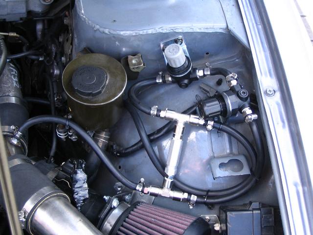
Since I was going to all the effort of upgrading the turbo unit, it made sense that while I replaced all the waste gate actuator lines, I should fit the mechanical boost controller and waste gate creep control valves that I have had collecting dust for more than 2 years, so I did. The three main components are the regulator valve, the pressure relief valve and the pressure release valve. The regulator valve is just like a tap which controls the flow/pressure of air to the waste gate actuator, by reducing the air flow, the system pressure needs to be higher to force the waste gate open, e.g. boost must be higher to open the waste gate. This unit becomes the boost contoller. The pressure relief valve is used to prevent waste gate creep by stopping air pressure operating the waste gate actuator until the boost pressure reaches a set level, (this level is fully adjustable up to 1 bar to ensure driveability is maintained). Stopping the waste gate slowly opening at low boost levels ensures all exhaust gasses pass through the turbo wheel, this makes the turbo spool up faster and reduces lag. The down side of the relief valve is, when pressure drops below the set level on the input side of the valve (e.g. when you change gear or take your foot off the gas pedal), the valve closes and traps the air already in the system. This has the potential to trap the waste gate open, losing power until boost rises above the set level and opens the valve again. The pressure release valve is used to specifically avoid trapping the waste gate open, when the air pressure drops off on the feed side of the valve, the valve automatically opens and releases the blocked air back into the line. When the pressure builds up again the valve is forced closed again. |
|||||||||||||||||||||||||||||||||||||||||||||||||
![]() |
|||||||||||||||||||||||||||||||||||||||||||||||||
| Left: The boost control assembly, the valves are reasonably temperature sensitive so they have been mounted within the cold air box unit. | |||||||||||||||||||||||||||||||||||||||||||||||||
![]() |
|||||||||||||||||||||||||||||||||||||||||||||||||
| Right: The finished installation, turbo, new pipework and boost control assembly. | |||||||||||||||||||||||||||||||||||||||||||||||||
| All valve and connection components were purchased from Norgren, the main valves where purchased overseas, but the balance were purchased from the Penrose branch, 3-5 Walls Rd, Penrose. Ph: 09 579 0189 |
|||||||||||||||||||||||||||||||||||||||||||||||||
| Parts List for Boost controller assembly: 1No. R07 - Regulator valve (boost controller) 1No. V07 - Relief valve (waste gate creep controller) 2No. Low pressure internal springs for both units above 2No. 18-025-003 - Mounting brackets 8No. 101150628 - 1/4 inch, 6mm hose fitting 1No. T55C2800 - Check valve (pressure release valve) 2No. 150202828 - 1/4 inch double adapter 2No. 160620028 - 1/4 inch female T connectors 1m 6mm I/D reinforced fuel line |
|||||||||||||||||||||||||||||||||||||||||||||||||
| The very helpfull chaps at Pit Stop on Wairau Rd were able to custom make all the new pipework required to reconnect the Turbo to the FMIC and AFM. The guys on the floor have a good handle on welding mods and doing tidy finishing work, Thanks guys. | |||||||||||||||||||||||||||||||||||||||||||||||||
![]() |
|||||||||||||||||||||||||||||||||||||||||||||||||
| Left: Layout diagram for the boost control assembly. 
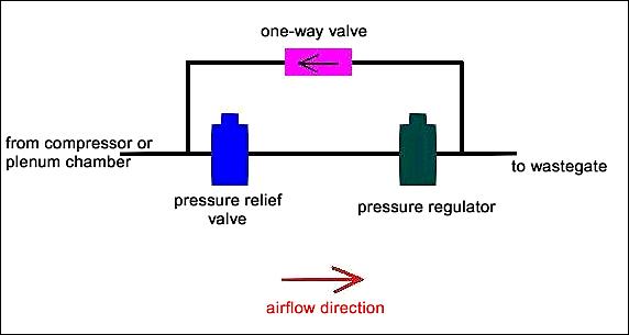
Ensure all components are installed in the correct order as shown otherwise the system doesn't work properly. |
|||||||||||||||||||||||||||||||||||||||||||||||||