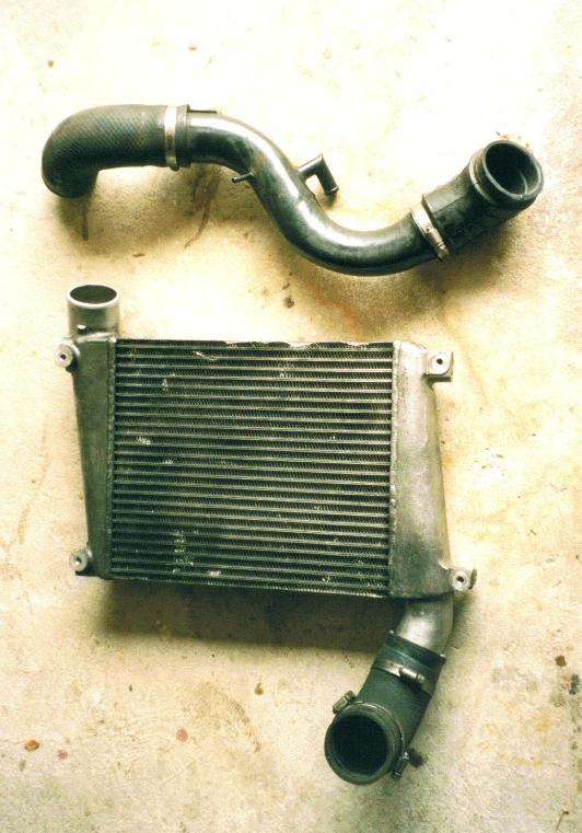
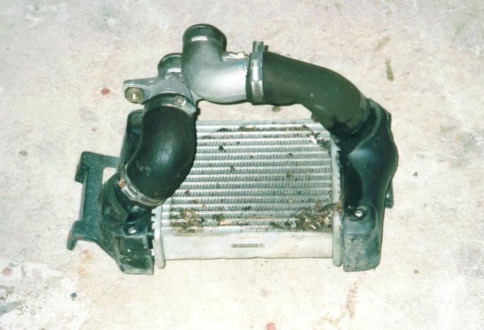
The inlet and outlet pipes suited to the Pulsar are completely out of place to connect within the front bodywork of the 200sx so a call was made to a friendly engineering sheetmetal company to cut the pipes off and plug the orginal holes.
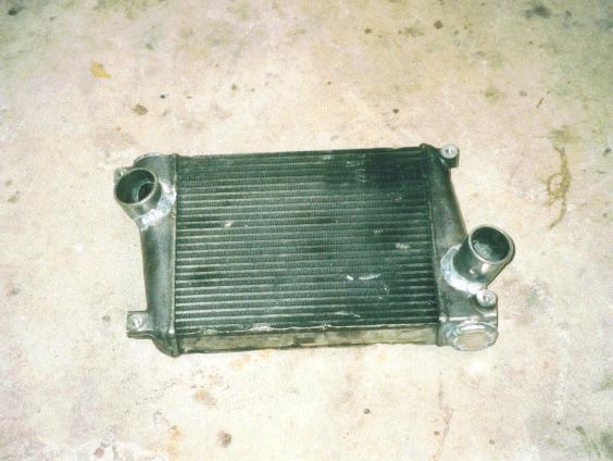
This left only the problem of where and how to remount the inlet and outlet pipes to allow easy plumbing based on the frontal cavity created in Stage 2 of the modification process. After measuring heights and angles that may work, I finally went with the pipe ends reconnected to the end tanks at 45deg in the larger portion of the end tanks. This also allowed the use of the soft bends I was given when I purchased the IC.
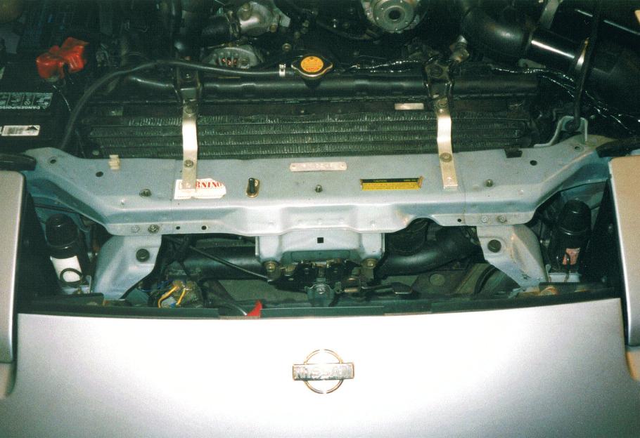
Each section was used to bolt to the lower 2 fixing points on the IC and then cut around some of the car bracing to fix to the main chassis cross rail. The 2 brackets were then painted black and riveted to the car chassis.
The upper mounts were fixed with 20mm x 5mm aluminium bar which was bent and drilled to suit vacant fixing points on the car structure, these were also painted black.
This ment the IC would be mounted between the bonnet latch unit and the front bumper still leaving a large cavity where the air-cond and radiator used to be placed. The air horns were mounted in this cavity.
Since the hole in the front of the car only covers about half the total IC height, a 75mm dia PVC pipe was ducted from the drivers side lower air vent (below the indicator and park lights) back into the bumper cavity and across the front of the IC at the top. The pipe was capped, glued and painted black. About 35 holes drilled in one side allows some air to flow through the upper part of the IC.
The reason a couple of large holes weren't drilled or cut in the front bumper to allow air to flow through the entire IC is because I don't want to change the exterior shape and style of the car.
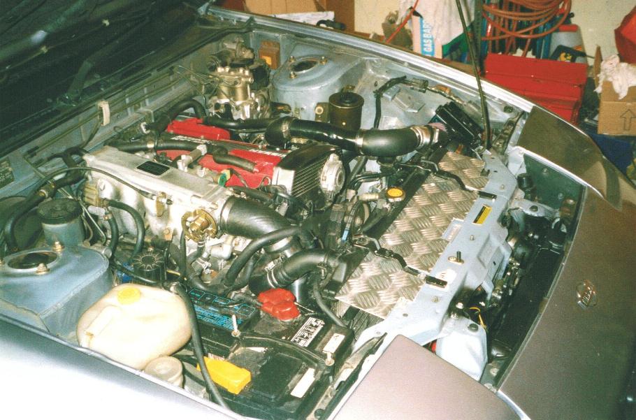
The pipe work from the turbo was flared from 50mm to 63mm at the first fixed bend. From there the 63mm pipe contained 2 soft bends and one steel bend to pass around the end of the radiator and infront of the air-con condenser to reach the IC. The Pod filter pic further down the page shows where the pipe work goes to reach the front.
The 63mm pipe continues from the IC via a soft bend to a customised rectangular stainless steel section with 63mm dia pipes at each end which fits under the battery tray.
The battery tray requires the removal of the bracing plate at the engine bay end.
2 soft bends and a final piece of stainless pipe (which includes the BOV outlet pipe) and you reach the manifold.
1No. square to 75mm round downpipe dropper
4No. 90 deg bends, 75mm dia
1100mm 75mm dia straight pipe
1No. 75mm dia round end cap.
1No. tube/pot glue
Paint (I used black to hide the pipe)
A form of fixing (I used black cable ties).
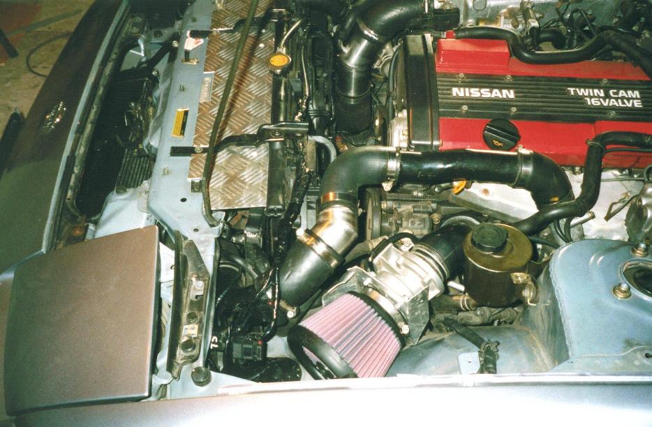
The Pod filter was chosen because it was cheap and not only had filter material to the diameter but had an open front end that was filtered. The front end of the Pod filter is directly over the new cold air duct formed with the removal of the original IC.
A cold air box will be formed around the Pod filter soon,
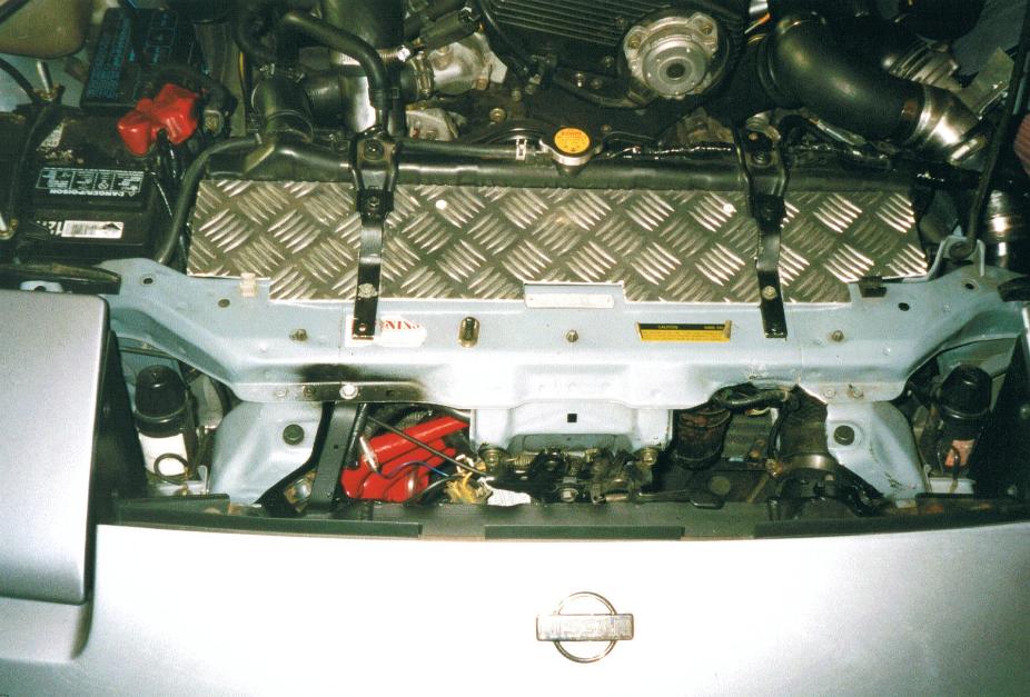
The chequer plate across the front is to control air flow, the twin fans pull air through the IC when keeping the motor cool.