 |
|
|
|
|
|
|
|
|
|
|
|
|
|
|
|
|
|
|
|
|
|
|
|
|
|
 |
|
|
|
 |
|
|
|
|
|
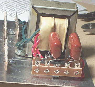
(Refer to page 22 ~27): Now, as for the B+ part here's how it looks like: |
|
|
|
 |
|
|
|
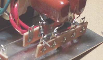
You will have to bend those 2 big 0.01MFD cap's lead on order to go through the outer terminal tabs. |
|
|
|
 |
|
|
|
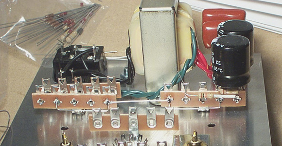
Now, install those 270K, 1K resistors before you put on those electrolytic capacitors. Make sure you have the polarity aligned correctly before you solder them onto the terminal tabs (refer to page24, 26 and 1/2 of 26): |
|
|
|
 |
|
|
|
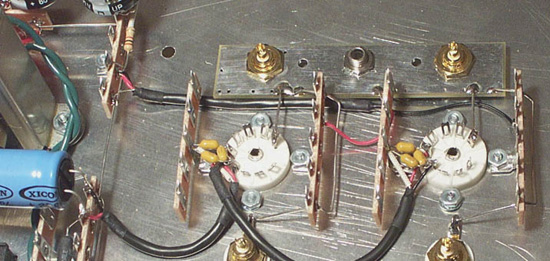
Now, as for the B+ wiring part (refer to page 29 and pic on page 30): make sure you have the B+ wiring shield ground wire connect to the ground plane close to the grounding nut. Also wire tube pin#9 of both sockets to the ground plane (A9 to H, B9 toQ), like this: |
|
|
|
 |
|
|
|
|
|
|
|
|
|
|
|