You are the visitor number:![]()
since 26/11/2000
By Miguel Lidón Plaza![]()
This web page shows the result of my project needed to finish my university degree. This is entitled Study of the Stability of an Artificial Satellite. The university career is Aeronautical Technical Engineering and my speciality is Aircraft. The career was studied at the Escuela Universitaria de Ingeniería Técnica Aeronáutica of the Universidad Politécnica de Madrid from Madrid, Spain.
 The
design of a space vehicle is a task that has multifarious and very
complex activities. One of the most important aspects is the
determination and control of its attitude or direction because
together with the study of its orbit constitute the general movement
of the space vehicle.
The
design of a space vehicle is a task that has multifarious and very
complex activities. One of the most important aspects is the
determination and control of its attitude or direction because
together with the study of its orbit constitute the general movement
of the space vehicle.
The fact that the space vehicle maintain a certain attitude is important, for example, in the need maintain a zero angle of attack during its impulse through the atmosphere or that acquires the necessary angle of attack (zero for ballistics income) prior to the entry in the atmosphere or the importance of the appropriate direction of the impulse for the modification of its orbit or its correct direction to send signs to The Earth or to point to stars.
Usually, the space vehicle is inherently unstable and it is submitted to torques engendered by its interaction with the environment and by the movement within the vehicle. Though the forces associated with these torques are not normally sufficiently large to affect the orbit of a space vehicle, the torques can affect significantly the attitude of the space vehicle. The torques of the environment (external) on a planetocentric satellite can be originate from the solar radiation pressure, from magnetic and gravitational planetary fields, and free molecular forces (if the satellite is sufficiently close to a planetary atmosphere). Exist the possibility also of impacts produced by meteorites and particles of dust. The torques that originate of internal movements can be engendereds by displacement of the load and by the movements and actions of the occupants as well as by the ejection of propellants and other liquid.
If a space vehicle in orbit is unstable, will degenerate if it is disturbed; if it is marginally stable (not damped), it will oscillate about a balance position; and if it is stable (with the external or internal damping), will return to the balance position after that the transient oscillation is extinguished.
 Although
an unstable space vehicle will be unacceptable, a space vehicle
marginally stable can be acceptable if the extent and the frequency
of the oscillations are small; a dynamically stable space vehicle is
the design goal. The stabilization techniques can be classified as
passive or active. The active stabilization devices, such as
thrusters, gyroscopes and reaction wheels, require an energy expense
and increase in the weight of the space vehicle and they can be
expensive; furthermore, energy supply is exhausted, the control of
attitude of system fails, the space vehicle degenerates, and the
mission will aborted.
Although
an unstable space vehicle will be unacceptable, a space vehicle
marginally stable can be acceptable if the extent and the frequency
of the oscillations are small; a dynamically stable space vehicle is
the design goal. The stabilization techniques can be classified as
passive or active. The active stabilization devices, such as
thrusters, gyroscopes and reaction wheels, require an energy expense
and increase in the weight of the space vehicle and they can be
expensive; furthermore, energy supply is exhausted, the control of
attitude of system fails, the space vehicle degenerates, and the
mission will aborted.
In addition to stabilization problem, there is an independent direction problem, generally a problem of active control, in which the space vehicle or a part of the equipment of the space vehicle must point to a specific direction. It is considered, for example, an exploration satellite of the Earth with cameras and infrared sensors that they should always point to the surface of the Earth. It can have also missions to investigate the Sun or other celestial bodies and navigation missions in which the antennae should maintain or acquire the required directions. Furthermore it is always the need of an appropriate direction before of the thrusting to put it in orbit.
Although, generally, the applications of the space vehicles are satellites in geocentric orbits, this study can be extended to orbits on other planets or other bodies, such as moons and asteroids, and to interplanetary transfers.
As has been mentioned, the operation of the space vehicle is submited to numerous disturbance forces that, if they do not act on the center of mass, produce a torque applied to the vehicle. The evaluation of these influences from the point of view of absolute magnitude and relative magnitude is an essential part of the task of the designer of the system of control and determination of attitude of the space vehicle.
Below they will be listed the principal external sources of disturbance of a space vehicle:
The internal torques are of greate importance in the control of attitude of the space vehicle, resulting from the exchange of momentum between internal mobile pieces. This not has any effect on the total momentum of the system, but it can influence and influences the sensors direction mounted in the vehicle and the circuits of control of attitude that they could be operating. Typical internal torques are:
Antennae
Solar panels
Movements of exploration instruments
Deployed arms and appendices
Ship crew
The passive stabilization techniques take advantage of basic physical principles and of forces that are produced spontaneously to design the space vehicle, reinforcing the effect of a force while reducing other. In effect, will be used the analyzed disturbing torques previously to control the space vehicle, choosing a design such that emphasize a torque and ease the others.
An advantage of the passive control is the capacity to achieve a very long life of the satellite, not limited by onboard consumable or, possibly, even by the wear and mobile pieces breaks. The typical disadvantages of the passive control are the relatively poor total accuracy and response something inflexible to changing conditions. Where these limitations will not be of interest, the passive techniques will operate very well.
These are some of the used techniques:
Concepts of control by feedback: The basic concept of active control of the attitude is that the attitude of the satellite is measured and compared with the wished value. The error signal so developed is used then to determine a corrective torque maneuver, that it is implemented by the actuators onboard. Since the external disturbances will follow occurring, and since the measurements as well as the alterations will be imperfect, the cycle will continue indefinitely. Some of the used methods:
The project consisted of the study of the movement of a solid with a fixed point for its application to the stability and control of an artificial satellite. From the theory of the Kinematic of the Solid is known that the general movement of a solid can be decomposed in each instant of time in an adjournment, with the speed of a anyone point of the solid (point O), more an instant rotation about a axis than pass by the point O. If are given the following conditions,
the point O belongs to the solid;
the point O coincides with the center of mass (CM) of the solid or it is a fixed point or its linear acceleration goes through the center of mass in each instant;
there is a reference frame S0 that it is bound to the solid and is moved with him;
the said frame of reference are principal inertia axis of the solid
the equations of the movement are simplified much being obtained the equations of Euler:
Due
to the first two conditions, will be chosen the CM as point O to be
sure that the second condition is fulfilled for any type of movement
of the solid. The reference system S0 will be chosen bound
to the solid, principal of inertia and centered on the CM of the
solid. Furthermore, due to the inflexibility condition of the solid,
its movement can be substituted by the movement of its ellipsoid of
inertia (though there is no indeed rigid bodies, especially the light
space vehicles, that are characterized by arms, antennae, retractable
sensors, and other appendices. Furthermore, the revolving bodies with
elastic blemishes will dissipate energy in one way that they can
change the direction of the body or the rotation axis, possibly
leading to the instability).
To obtain the simulation of the movement of the space vehicle in large part of the situations indicated in the introduction, three computer programs were developed to solve numerically the part of mass geometry (moments and principal inertia directions) and the dynamic part (equations of Euler) being effected the data output in text files and showing on screen the movement of the ellipsoid of inertia in fixed frame (S1: CMXYZ), mobile frame bound to the solid and principal of inertia (S0: CMxyz) and in frame bound to the flat invariant (S': Qx'y').
The study effected in this project is as much respect to the qualitative behavior as quantitative of a space vehicle.
 When
the resulting of forces applied to the solid does not produce
torques, the resulting movement has certain peculiarities. The
momentum and kinetic energy are constant, exists an invariant plane
that it is perpendicular to the momentum vector and tangent at each
instant to the ellipsoid of inertia; the tangency point is contained
on the instant rotation axis of the movement and is called pole.
When
the resulting of forces applied to the solid does not produce
torques, the resulting movement has certain peculiarities. The
momentum and kinetic energy are constant, exists an invariant plane
that it is perpendicular to the momentum vector and tangent at each
instant to the ellipsoid of inertia; the tangency point is contained
on the instant rotation axis of the movement and is called pole.
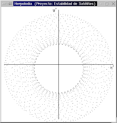
The points of the ellipsoid that they have been in touch with the plane form a curve designated polhode and the corresponding of the plane form a curve designated herpolhode. Exist other ellipsoid that it originates from the equation of the momentum whose intersection with the ellipsoid of inertia is the curve polhode.

 If
the solid is turning about its axis of greater moment of inertia or
about its axis of smaller moment of inertia, a small disturbance that
shifts the spin axis from its position cause that the spin axis
oscillates in a way more or less stable around inertia axis. But if
the spin is effected according to the axis of intermediate moment of
inertia, a small disturbance cause that the spin axis change
ostensibly of direction. All this can deal in the figure with the
form of the curves polhode.
If
the solid is turning about its axis of greater moment of inertia or
about its axis of smaller moment of inertia, a small disturbance that
shifts the spin axis from its position cause that the spin axis
oscillates in a way more or less stable around inertia axis. But if
the spin is effected according to the axis of intermediate moment of
inertia, a small disturbance cause that the spin axis change
ostensibly of direction. All this can deal in the figure with the
form of the curves polhode.
Three computer programs were developed in C language under Linux
operative system.

The first one, called inercia v1.0, reads a text file where are described several simple geometric solids that form the solid to study. There is a set of simple geometric solids defined: cone (cono in spanish), sphere (esfera), cylinder (cilindro) and square base prism (paralelepipedo); and the user can define other solids without need of modifying the program. It is possible to describe solid not alone compounds by simple solids but also compounds by solid described at the same time in other .dat file. This is possible thanks to the fact that the inercia program use recursion. They can be indicated until a total of 100 simple solids.
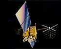
For example, in the text file called voyager.dat you can see in each line: the type of simple geometric solid, its density, the position of its centre of mass, its orientation according to the angles of Euler and its geometric parameters. The fourth line does not correspond to a simple geometric solid, it indicates the path to other data file. This is possible thanks to the recursion used in the inercia program.
The output of the inercia program is other data file (voyager.ine in the example) containing the main quantities of inertia and the corresponding main inertia directions. Also, the user can make this file with a text editor.
This program, as opposed to the others two, does not require graphic environment (XWindow) for its execution.
 dibuja
v1.0
dibuja
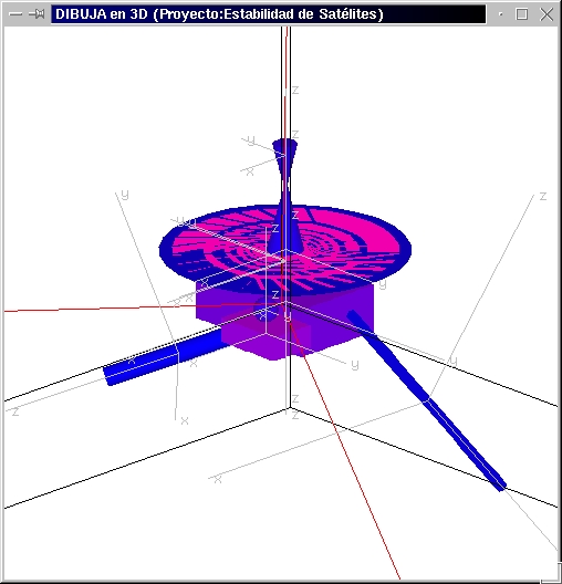
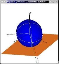
v1.0During the process of creation of the .dat file, it is very useful to use the dibuja program (it is the second program) to watch the solid. dibuja v1.0 program only is capable of drawing cones, cylinders, spheres and square base prisms; to add new solids is necessary to change the source code of the program and add a new subroutine.
The picture shows the output of dibuja program applied to the voyager.dat file.
Finally, the third program, called polodia v1.0, reads the voyager.ine file and creates three graphic windows where the part graph of the calculations will be shown. In several text files will be kept information in each time instant on the angular speed w(t) (omega.sal file), the momentum HCM(t) (momento_cinetico.sal), kinetic energy Ec(t) (energia.sal), the polhode curve (polodia.sal) and the herpolhode curve (herpolodia.sal).
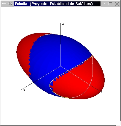
The first image above shows, in CMxyz frame, the ellipsoid of inertia of the solid in blue colour and the ellipsoid from the equation of the momentum in red colour, the intersection of both is the polhode curve.
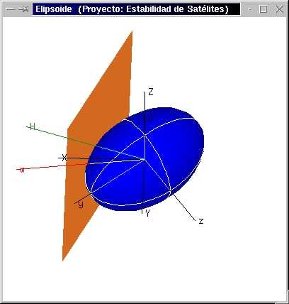
The second image shows, in CMXYZ frame, the ellipsoid of inertia, the angular speed (w) and momentum (H) vectors and the invariable plane.
The third image shows, in Qx'y' frame, the Herpolhode curve on the invariable plane.
In addition to the data of the .ine files, polodia program requests by keyboard other data as are the angular speed at the initial time and the time increase to solve the differential equations in a numerical way by the method of Runge-Kutta.
 During
the execution of the polodia program, the user can interact
with it through the keyboard. For example you can to change the
direction of the pictures, to zoom, to show or not the invariable
plane, to show or not the ellipsoid of the momentum equation, etc.
During
the execution of the polodia program, the user can interact
with it through the keyboard. For example you can to change the
direction of the pictures, to zoom, to show or not the invariable
plane, to show or not the ellipsoid of the momentum equation, etc.
Clic on the picture to see a 8 seconds mpg video showing the evolution along the time of the ellipsoid of inertia.
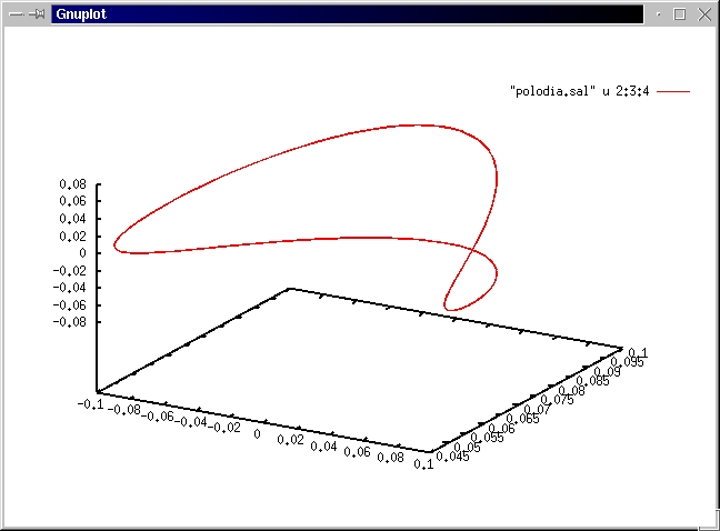
The possibility of read the files of output data (.sal) with programs as gnuplot must to be emphasised. It can be done even while polodia program is being executing; but it must be in pause. It can be visualized, with gnuplot, things as:
![]() kinetic
energy versus time;
kinetic
energy versus time;
![]() herpolhode curve in the space
(CMXYZ fixed frame) or in
the plane (mobile frame
Cmxyz );
herpolhode curve in the space
(CMXYZ fixed frame) or in
the plane (mobile frame
Cmxyz );
![]() polhode
curve;
polhode
curve;
![]() the momentum module
versus time;
the momentum module
versus time;
![]() the
components of angular speed in
fixed frame (CMXYZ) versus time;
the
components of angular speed in
fixed frame (CMXYZ) versus time;
![]() and
many things but ...
and
many things but ...
 Every
time you can put the program on pause mode and use dibuja
program to see the solid in the current time instant. As can see in
the picture.
Every
time you can put the program on pause mode and use dibuja
program to see the solid in the current time instant. As can see in
the picture.
DISTURBANCES
It is possible to introduce disturbances in the movement of the solid, as can be: directly applied torques in the direction of the fixed frame (CMXYZ) as well as in the mobile frame (CMxyz), changes in the density, changes in the position of the centre of mass and changes in the direction of some of the simple solids that form the solid to study.
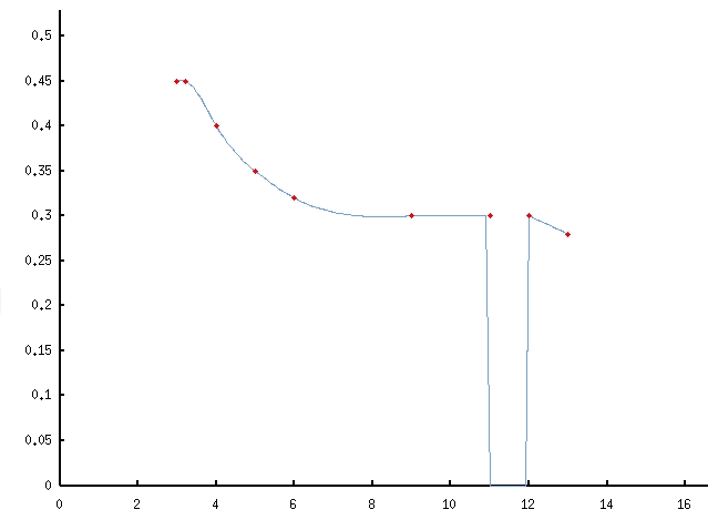 The
disturbance functions are defined through points and polodia
program create splines interpolation functions and they can be so
complicated as shows the picture.
The
disturbance functions are defined through points and polodia
program create splines interpolation functions and they can be so
complicated as shows the picture.
In text files with the extension .per are described the disturbances to produce. These files have a format as you can see in voyager.per text file. It is indicate the type of disturbance, the initial and final time of the disturbance, the solid which it affects (if it proceed), the number of sections of the spline function and the number of points of each section followed by the points that form each section. They can be written until a total of 100 disturbances.
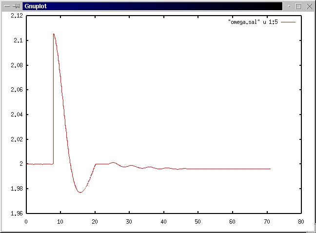
If it has been executed polodia program with disturbances, several text files are created with information in each time instant about the applied torques (moments.sal file), the density of the simple solids (densidad.sal), the position of the centre of mass of the simple solids (xcg.sal, ycg.sal, zcg.sal), and the angles of Euler of the simple solids (psi.sal, theta.sal, phi.sal). The same as with the rest of .sal files, they can be read by the program gnuplot and it can shows things as
![]() angular
speed versus time;
angular
speed versus time;
![]() the "y"
component of the centre of mass of the solid number 5;
the "y"
component of the centre of mass of the solid number 5;
![]() and many things but ...
and many things but ...
ORDER OF MAGNITUDE OF THE NUMERICAL ERROR
The calculation error that are procured vary of some values to other, depending of the quantity of calculations that they will be necessary to obtain them. Thus, for example, with an initial angular speed of the order of 5 rad/s, and a time interval for the integration of 0.001s, a relative numerical error from kinetic energy of 10-15 is obtained but a relative munerical error of the components of the momentum (in coordinates of the fixed frame) of the order of 10-5 . If is wanted greater precision in the calculations can be reduced the integration interval, but it slow down the program.
The title of the project is "Study of the stability of an artificial satellite", this has become in the development of some computer programs that facilitate the study of the movement of any rigid solid with respect to its centre of mass. From this point is possible to apply this work to the study of the different space vehicles movement with different configurations and initial conditions; in a way rapid and versatile.
The programs developed in my university course end project forms a tool of great potential to understand and to study the movement of a solid with respect to its centre of mass. They can be defined solid, in principle, so complex as you wish and introducing some initial conditions of position and speed, see the evolution along the time. The results are the polhode and herpolhode curves, position(t), w(t), HCM(t), Ec(t). Also, though with certain limitations, you can interact with the solid from the foreign, applying torques and mass and geometry changes.
Resuming, it can be said that the following topics were encompassed:
Physical
mechanical: movement of the rigid solid
mass geometry
Mathematics
numerical calculation
matrix calculation
differential equations
Data processing
graphics programming
events management
recursion
I desire to express my gratefulness:
![]() to Mr. Bruno Ramiro Díaz
and Mr. Ángel Álcazar
de Velasco Rico titular teachers of the department of Aerotecnia
of the E.U.I.T. Aeronáutica, my tutors of the project;
to Mr. Bruno Ramiro Díaz
and Mr. Ángel Álcazar
de Velasco Rico titular teachers of the department of Aerotecnia
of the E.U.I.T. Aeronáutica, my tutors of the project;
![]() to Marián and Ramón, commissioned of the loan service
of the library of the E.U.I.T.Aeronáutica;
to Marián and Ramón, commissioned of the loan service
of the library of the E.U.I.T.Aeronáutica;
![]() to Chus, commissioned of the data processing classroom of the
E.U.I.T.Aeronáutica;
to Chus, commissioned of the data processing classroom of the
E.U.I.T.Aeronáutica;
![]() to all those which have made and made possible the existence of
Linux;
to all those which have made and made possible the existence of
Linux;![]()
![]() to Pablo by the copies of CD - ROM;
to Pablo by the copies of CD - ROM;
![]() and
above all to my family by their patience and support.
and
above all to my family by their patience and support.
![]()