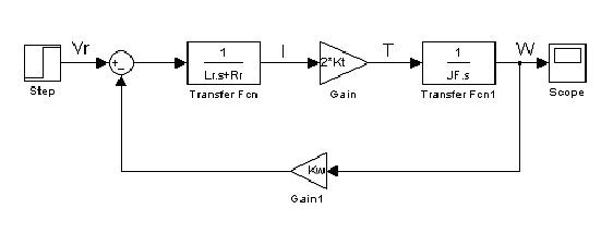
By using the forward motion model and the motor characteristics the transfer function of the system can be found. This will enable the characteristic equation to be calculated determining response values such as speed. Using that
T(s) = C(s) G(s) / 1 + C(s) G(s) H(s) where G(s) = 2Kt / (Lrs + Rr)Jfs + 2KtKw
and C(s) = 1 H(s) = Kw
The characteristic equations are shown in section 6.3 Analysis of control loop implementation. The system of the mouse is mainly designed around the control of the mouse�s position. A method of identifying the position through the signal from the sensors positioned at the front of the mouse. Through conversion of the signal in the sensor circuit the signal is changed to V� that is proportional to the angle of the mouse. The mouse angle control guidance can be calculated using motor equation. Using the fact that guidance control equation is G�(s) = Gf(s).(2*rw/ws)and Go(s) = �(s)/V�. This assumes that we have angle transducer that is linear and it has an output of 1V per radian. Using that rw (wheel radius) = 21 mm and w(width of mouse) = 137 mm these can be put in the equation. The results of the equation and control are shown in section 6.3 of the analysis.
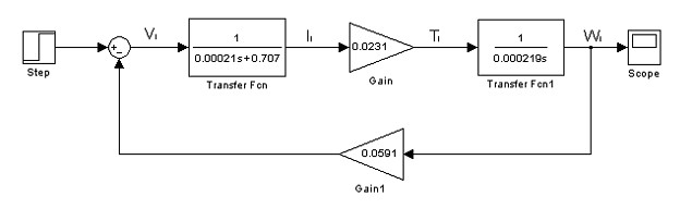
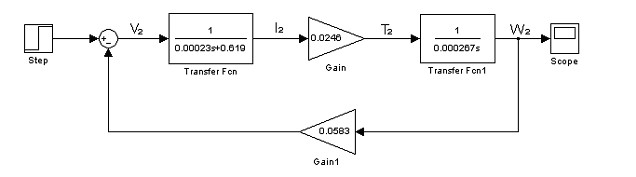
Simulating the forward motion will show the response of the motors. The motors will be directly controlled by the sensor circuit. Therefore the response of the motors must be similar to allow the direction of the mouse controlled by the motors. The slightly different parameters do created slightly different responses but these affects are so minor they do not affect the system. The variations can also be corrected by modifying the sensor circuits to suit each motor. The motor and angle control are now considered in the analysis of results.
5.5 The Motor Drive Circuit
The motor drive circuit is connected directly to the sensor circuit. The output of the sensor circuit provides an adequate voltage to drive the motor however the current is the issue. Through the use of a transistor the problem can be solved. Again there are many different ways to design a motor circuit to meet the specification of the mouse. The question when designing the motor drive circuit is whether a bidirectional design is required. The mouse will be going down a slope around the circuit and may need to be braked down the hill. The gravity pulling the mouse down the hill will mostly likely take over from the current powering the motor therefore the angle control could be lost. The motor speed might not be affected by change in voltage as gravity has taken over. If a corner was placed at the bottom of the hill it would have the potential to cause the mouse to loose the track. Using a bidirectional motor circuit would prevent the mouse from loosing control. However the friction of the hill should slow it down enough to allow control of the direction of the mouse. The track on the hill is straight therefore the direction of the mouse should not vary much off the course. This implies that a simple motor drive could be used. This investigation looks at two designs that were considered to be the best, a simple motor drive and a bidirectional motor drive.
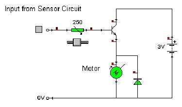
The first motor drive circuit is the simple motor drive utilising a single transistor. The transistor is required to provide enough current to drive the motors. A Darlington pair would provide more gain of current however the one transistor supplied enough current in testing the drive the motors. The transistors used have fairly high gain and let enough current through to drive the motors. The base of the transistor is connected to the output of the sensor circuit and the collector is connected to another power supply. The emitter is connected to the motor. When enough voltage from the sensor circuit is reached the transistor conducts so the power from the batteries adds to current and powers the motor. The sensor circuit will control the motor by varying the voltage which will in turn affect the current supplied to the motor. This will allow the mouse to move and turn according to what the sensors pick up. Fig.11 shows the circuit layout for the motor drive circuit. The voltage supplied to the motor must only be a maximum of three volts. The rating of the motor states it can only take a maximum of three volts otherwise the motor would be damaged. Therefore the power supply to the transistors shall only be three volts. The diode is placed across the motor as the motor has inductive coils inside that still conduct when motor is stationary. The diode protects the circuit and motor from being damaged. The variable resistor at the input to the motor drive is used to vary the current supplied to the transistor therefore allowing the change of standard speed of the motors for the generated voltage by the sensor circuit. With the combination of the variable resistor and the variable resistor for the gain of the last op-amp, on the sensor circuit, the mouse speed can speed and response can be fine tuned.
Fig.11: First motor drive circuit design
 |
|
|
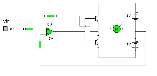
An alternative motor circuit design is to use a bidirectional circuit. This circuit will have the advantage of being able to brake down the hill and have more control of the speed of the motors. The circuit is essentially very similar to the previous circuit using two transistors to supply enough current to power the motors. However the circuit is setup to be able to reverse the direction of the motors and therefore utilises a �3V supply. Fig.12 shows the alternative circuit diagram.
Fig.12: Bidirectional motor circuit design.
 |
|
|
Both motor circuits meet the specification of the mouse. The bidirectional drive circuit has the advantage of allowing the system to break. However the amount of batteries required to do this is double that of the first motor drive circuit. Considering that two motor drive circuits are required, the number of extra batteries needed adds to the weight of the mouse significantly. The mouse design chosen is to be light weight as possible to make it around the circuit as fast as possible therefore it is best to use the first circuit design.
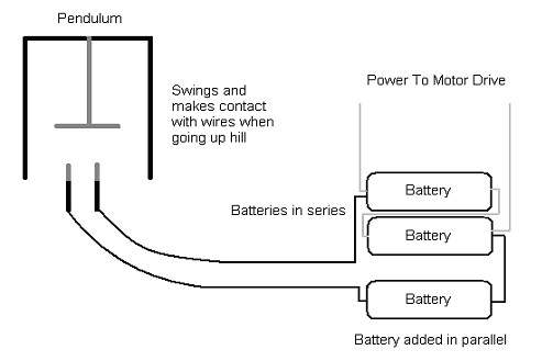
Having considered all the circuits for the mouse design it is clear that the number of batteries required is high. This means the mouse will be reasonably heavy and may have problems reaching the top of the hill. To solve this problem a simple method to add current to the motors is required. By using a pendulum design on the mouse that connects extra batteries to the motor drives will increase the current supplied. This will give the extra power required to drive the mouse up the hill. Using a simple pendulum that swings back a metal ball when it reaches a hill. This will connect two wires which in turn connects a battery in parallel to the motor supplies. This will add more current to the motor and give the motors the extra power to make it up the hill. This method can be used to add an extra battery to each supply. Fig.13 shows a diagram showing the up hill power control through the use of the pendulum.
Fig.13: Speed control Pendulum
 |
|
|
Now the circuits have been decided for the project the next stage is to test and build them. The best method is to build them on bread board so they can easily be modified to make any adjustments required. The best way is to construct the circuits individually, i.e. the sensor circuit only and test that. This limits any faults that may occur to certain sections of the full project. It also makes it easier to test the individual sections and work as group testing a section each. Once testing has been completed the circuits should be built on strip board reducing the size or circuit board required, the weight of the board, allows the components to be fixed properly and improves the layout of the circuit. The following section 6. Analysis of results goes through each part of the investigation testing the circuits ensuring the required outputs are created.
|
|
Contents |
Introduction |
The investigation |
Analysis of Results |
Conclusion |
Appendix A |
|
|
| |