P-P � Peak to Peak
3. Introduction:
The aim of this design exercise is to design and build an electro-mechanical system that will allow an electronic mouse to follow a track. The project will be built and tested in a real world environment. The final test will include the fastest time of completion of the circuit. The track carries a one amp guidance signal at 20 KHZ, which will be used to guide the mouse. The mouse will designed around the use of the magnetic field created by the wire and the chassis�s available. There are two types of chassis which can be chosen, which require different designs to control. The control choice of the mouse can be analogue or digital control. The characteristics of the track must be considered when designing the mouse, including corners and hills. There are many other considerations of the design, such as batteries required and sensors. The investigation covers all these areas of designs and analyses each section.
4. Theory:
The response of the mouse system of speed and angle control can be simulated and controlled by control loop implementation. The mouse can be modelled and through the use of the characteristics of the system a characteristic equation can be found. This will allow certain values to be found, such as speed. The model can then be simulated using MATLAB Simulink to provide graphical data for the system.
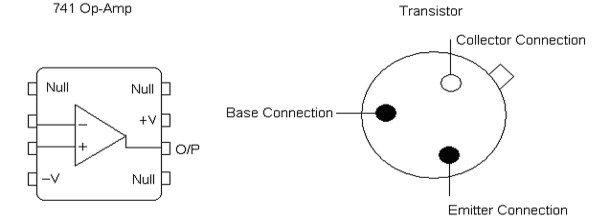
This investigation uses the 741LN operational amplifier for all op-amps used in the circuits. This op-amp is ideal for the project as it can take the input voltages given by the circuit without damaging the component. The ranges of voltages used by the circuit are all in the tolerance of the op-amp. The op-amp is required to be connected up to the circuit. Fig.A shows the layout of the 8 pin chip that is the 741 op-amp. The investigation also requires the use of transistors in the motor drive circuit. To build the circuit the pin layout for the diode used in the circuit is shown in Fig.A. Knowledge of how amplifiers and transistors work is required when designing the mouse. However all gains that need calculating, connections required and their performance in the circuit is explained in the investigation.
Fig.A: Pin layout for 741 and Transistor
 |
|
There are two different chassis�s available to choose from. The front wheel steering chassis uses a powerful motor for the drive and another motor to control the steering mechanism at the front of the chassis. The differential chassis has two motors that can only take a maximum of three volts. Any higher voltage than this will damage the motors so they will no longer work. The motors also contain a 15:1 gear ratio and have two wires from each that are fixed to them. These are used as the input and output of the motor. They cannot be soldered to the mouse circuitry as the chassis must be able to be detached at any time form the circuit. The pillars on the chassis shown in fig.1 allow the circuit board to be fixed onto the chassis using holes in the circuit board. The board can then be removed at any time. The motors must therefore use connector blocks to connect to them output of the circuit.
|
|