|
|
|
|
|
| Mouse Design Exercise: Investigation |
|
|
|
|
|
Contents |
Introduction |
The investigation 2 |
Analysis of Results |
Conclusion |
Appendix A |
|
|
5.1 Introduction and Specification of Investigation
This investigation looks at the design and build of an electronic mouse that follows a track. The mouse must go round a standard track under its own power and guidance. This is an electro-mechanical system design project that will be built and tested in a real world environment. The track carries a one amp guidance signal at 20 KHz. This will be used to direct the mouse around the track. It will be between ten and twenty meters long. It consists of a number of challenging features including long straights for speed testing, hills with a maximum of 15 degree slope, some corners onto and off hills and corners with a minimum radius of 1.3 metres. The aim of this investigation is to design an electronic mouse that will follow this track and complete a circuit in the fastest time possible. However when designing the mouse the following aspects and specification must be considered.
The first key consideration to design the mouse is which mouse chassis should be used. There are two different mouse chassis to be considered, the differential drive chasisy and the front steering thing.
Fig.1: Diagram showing the mouse chassis.
 |
|
|
Key aspects to consider when designing the mouse includes battery life, voltage and current, the weight of the vehicle, the speed for cornering and straights, mouse drive torque for hills, the motor characteristics, and the sensor positioning. There are three main blocks that the design will include. The sensor signal conditioning to gets suitable feedback signals for closed loop control, control loop implementation (i.e. gains and dynamic controller elements) and Power drives for the motors. The characteristics and availability of components for the three main blocks will have to be considered in detail.
The sensors provided for this investigation are two small pick coils. These can generate an output, of the order of 100mV p-p, when placed close to the track. The sensors can be placed in any position on the mouse to produce the best signal. Therefore the best position for the sensors must be considered in the investigation. There are two different types of mouse to choose from, front wheel steering and differential. This investigation looks at the implementation of the differential mouse. The motors on this vehicle are only to be driven up to three volts at each set of motor terminals. The mouse must be designed to get through each track stage, to complete the whole track and complete the rack in the quickest time possible.
To design a mouse to meet specification of this investigation it will have to be considered in stages. The first stage to look at is how the mouse will direct itself around the track using the sensors. The type of signal needs to be considered and how this can be used to control the mouse.
5.2 The Sensors
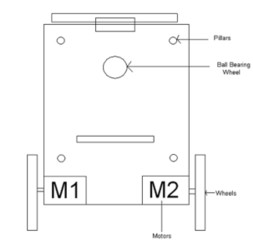
The mouse needs to be able to pick up the track and be able to use that to guide itself around the circuit. To do this a form of sensor is required to pick up the track. The track has a current flowing through it, which produces a magnetic field caused by the charge in motion. The changing magnetic field induces a voltage in any coil. The voltage induced is directly proportional to the rate of change of the magnetic field. The track therefore produces a changing magnetic field that can be used to induce a voltage. This voltage can then be amplified and used to control the direction of the mouse. The sensors that can meet this requirement are inductors as they are small coils. The inductors are small pick up coils that will generate a small amount of voltage induced by the current in the track. The closer the sensor the higher the voltage produced. The position of the sensor on the mouse is vital. The closer to the track the more voltage is produced which is required for the control of the mouse. The orientation of the sensors must also be considered to produce the maximum voltage. The sensors must perpendicularly cut through the magnetic field which produces the greater affect to induce voltage. Fig.2 shows the positions of the sensors compared to the track.
Fig.2: Diagram Showing the Sensor Positions
 |
|
|
As a group the chosen mouse chassis was the differential mouse and was selected to be rear wheeled drive. The best position for the mouse sensors would be at the front of the vehicle. Having the sensors at the front of the mouse allows it time to react to the senor input and correct the mouse direction. If the sensors were at the back the mouse would react slowly to turns in the track and produce a very unstable turning pattern. The mouse would drive off the circuit track at corners as the sensor would detect straight track at the back and would not have enough time to turn back. Having established the general position of the sensors a more accurate position is required. The most voltage that can be generated is required. So setting the vertical distance is simple as setting them to the minimum ground clearance. The maximum hill slope is of 15 degrees, by setting the sensors at a minimum 10mm away from the ground gives enough room for the mouse to have ground clearance to make it up the hill. The next stage is to measure the voltage produced by the inductors at distances horizontally from the track. This is required to set them along the front of the mouse to produce the best angle control of the mouse. Fig.14 in the analysis section shows the table of results of the voltages produced at different horizontal distances with a set vertical distance.
The results in fig.14 show that the inductor generates less voltage as it moves further away from the track. The position of the sensor must generate a sufficient amount of voltage to control motor speed. The analysis uses the results to determine the best positions of the sensors away from the front centre point of the mouse. The distance of the sensor must still be enough to drive the mouse with the voltage produced but still have enough variation to control its direction by slowing or speeding the motors. The analysis considers and sets the sensors at the most appropriate position.
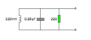
Just using an inductor to pick up voltage from the track creates a problem of noise. The noisy signal would then be amplified further in the rest of the circuit so it is important to keep it to a minimum. Using a resonant circuit, by placing a capacitor in parallel with the inductor, reduces the amount of noise picked up. However this circuit only picks up a specific frequency which may cause a problem as the supplies to the track can be up to �5% out of the 20 KHz frequency. Therefore the ideal circuit to use is a damped tuned circuit. This is created by adding a resistor in parallel to the capacitor and the inductor. This causes dampening and widens the frequency pick up of the sensor system. The inductors were provided for this project. The given value of the inductor is 220�H. Using the formula v (1/Inductance*Capacitance) = 2*pi*frequency. Setting the frequency to 20 KHz and the inductor at 220�H then the capacitor value can be calculated. The calculated value of the capacitance of 0.28�F will be used in the circuit. The resistor has to be added to allow dampening; using a 220 ohm resistor will add sufficient dampening to pick up the desired frequencies. Fig .3 shows the circuit that shall be used with the inductors to detect the position of the track.
Fig.3: Showing the sensor configuration using a damped tuned circuit
 |
|
|
A signal from the track has now been established but this must be implemented to control the direction of the mouse. A sensor circuit must be created to use the induced voltage from the sensor configuration to generate the required signal to control the speeds of each motor to control the mousse direction.
5.3 The Sensor Circuit
The sensor circuit is vital for the mouse. Using the sensors described above the signal they produce must be manipulated for use in this project. It has already been established that the average maximum voltage pick up from the track is 100mV peak to peak. This signal is not large enough to do anything with for the project. This investigation looks at two methods of dealing with this stage in the circuit. An alternate method is considered to see which will be best suited for this project.
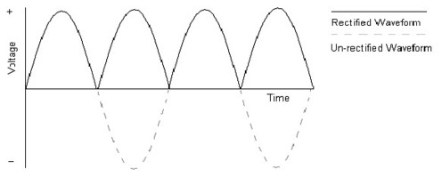
The first design firstly deals with the signal, which needs to be amplified. Using an op-amp this can easily be achieved. Using a gain of 100 then the output should be ten volts, which is plenty to use through out the rest of the circuit. The next thing to consider is the voltage signal required. This signal is going to be sent to the motors to control its speed. Therefore an alternating signal is unwanted for the control of the motors. A DC signal is required, which means an AC to DC converter is required. There are many forms of circuits to achieve this. However a simple but effective circuit would be to use a full wave rectifier. Fig. 4 shows how the full wave rectifier alters the wave form. The rectifier only allows positive voltage though the diodes. This means when the voltage reverses it is lost at the output. However the full wave rectifier uses another set of diodes to take the voltage as positive form the opposite supply rail when it has reversed direction of the voltage from the original supply rail. This new voltage is added to the original to make the signal all positive.
Fig.4: Fully rectified waveform.
 |
|
|
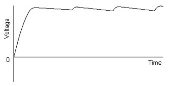
The full wave rectifier makes use of four diodes, which means there is considerable voltage loss. Therefore a second amplifier after the rectifier is required to increase the voltage. A simple non-inverting op-amp can be used. Setting the voltage gain to two will generate the required voltage. However if the feedback resistor is a variable resistor then the gain can be altered to create the ideal voltage. Since there will be the need for two sensor circuits they will need to be matched voltage outputs so the mouse does not drive of the circuit with one wheel faster than the other. The variable resistor will allow this to be achieved. The next stage is to smooth this voltage out so it becomes a steady line voltage. This achieved by using a low pass filter. This will be set to smooth the voltage so it becomes a small ripple voltage as shown in fig.5. The smoothing capacitor is only added after the amplifier as the ripple affect would be emphasised by the amplification. Fig.6 shows the circuit diagram of the first design idea.
Fig.5: The output steady state voltage (ripple voltage)
 |
|
|
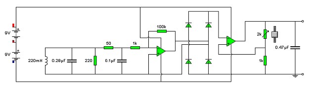
Fig.6: Sensor Circuit Design Using Full Wave Rectifier
 |
|
|
The circuit shown in fig.6 shows the use of many resistors and capacitors that all need specific values. The values of the sensor section are chosen to pick up specific frequencies as described above. The first low pass filter after the sensor is used to reduce the noise created by the circuit�s wires before being amplified. A low value resistor is picked so the voltage dropped is minimal. As noise frequencies want to be extracted frequencies of above 30 KHz want to be removed. Using the resistor value and the frequency value the capacitor can be calculated. Using Angular frequency (w) = 1/(Resistance(R) * capacitance(C). Therefore 1/(R*w) =C. So using w=2*pi*f then capacitance required is 1/ (50*2*pi*30000). The capacitance calculated is 0.1�F. The gain of the op-amp is -Rf/R2, shown by the 100k (Rf) and 1k (R2) resistor on the op-amp. The resistors were picked so the gain would be 100 increasing the voltage of the input signal to 10 volts. However the voltage would saturate due to the supply voltage to the amplifier. The voltage may be inverted but this does not matter as the wave has not been rectified. There is a significant voltage drop across the diodes so the second op-amp is set to double the voltage. This is non-inverting op-amp as a positive voltage is required to drive the motors. The gain of a non-inverting op-amp is calculated by 1+ (Rf/R2). Rf is shown by resistor connected to the output of the op-amp. The variable resistor is used to vary the gain of the op-amp so both sensors can be matched when built. The final capacitor was selected to smooth the output voltage. Therefore the low pass filter was set to 16 KHz so the 20 KHz signal is smoothed. A 0.47�f capacitor was selected to achieve the smoothing affect of the output signal.
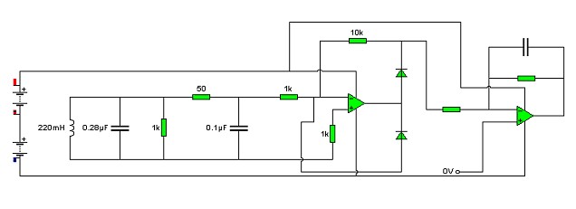
There are many ways to achieve the sensor circuit objectives. The alternative design considered was to use a precision half wave rectifier after the sensor inputs. Then using a simple low pass filter constructed using an op-amp the signal was smoothed to become a steady voltage. The op-amps provide good gain and without the use of separate diode rectifier there is less voltage lost. The alternative circuit design is shown in fig.7. The design does have its advantage of less power loss but the first design uses a full wave rectifier that should reduce the ripple affect. Both were considered looking at the advantages of the each of them. In this case the full wave rectifier was used as this was a slightly simpler set-up. The full wave rectification should produce a less rippled affect for the wanted steady voltage. The project needs to be as light as possible. The fewer components required the lighter the mouse is, very slightly increasing the speed. The reduced number of components also reduces the amount of noise created by the system. Both designs try to use as little components as possible and the difference in numbers between them is minimal. The sensor circuits will be connected to motor drive circuits of opposite sides therefore controlling the speed of each wheel. So when the mouse deviates away from the track then the voltage reduces to the opposite wheel slowing it down on one side. The faster wheel on the opposite will drive it back on course so the sensor picks up equal voltage again to drive straight.
Fig. 7: Alternate Sensor Circuit Design Using Precision Rectifier
 |
|
The first sensor circuit can be built using a variety of methods. It can be built on a printed circuit board if the facilities are available. However it easier to make the project on breadboard, which can be altered at any time and tested easily. This construction is usually a temporary measure as building the circuit on strip-board reduces it size and ensures components are fixed. The best method is to build and test the circuit on breadboard and then once satisfied with the results it can be built on strip built. This was done for first circuit and the results of the build are shown in section 6.2 Analysis of results.
Continue
|
|
Contents |
Introduction |
The investigation 2 |
Analysis of Results |
Conclusion |
Appendix A |
|
|
| | | | | | |
|
|