SNES Gamepad Interpreter | ||||||
| <<< Home | Disclaimer | Hardware Theory | Software Theory | Data | Reference | Links >>> |
| Abstract | <<< Back |
|
The AVR SNES Gamepad Interpreter can work as a basic control interface wherever high-speed controls are needed. Just like the Playstation Gamepad Interpreter that would follow, this project can read from the gamepad and use that data for a variety of unique purposes. |
| Disclaimer |
|
ALL INFORMATION WITHIN THIS DOCUMENT IS PROVIDED "AS IS" AND WITHOUT ANY EXPRESS OR IMPLIED WARRANTIES, INCLUDING, WITHOUT LIMITATION, THE IMPLIED WARRANTIES OF MERCHANTIBILITY AND FITNESS FOR A PARTICULAR PURPOSE. I DO NOT GUARANTEE ANY INFORMATION IN THIS DOCUMENT IS ACCURATE, AND IT SHOULD BE USED FOR ABSTRACT EDUCATIONAL PURPOSES ONLY. THIS SOFTWARE AND DOCUMENTATION IS FREE OF CHARGE. COPYRIGHT (C) 2005 BY BRADY MAYES. ALL RIGHTS RESERVED. REDISTRIBUTION AND USE IN SOURCE AND BINARY FORMS, WITH OR WITHOUT MODIFICATION, ARE PERMITTED PROVIDED THAT THE FOLLOWING CONDITIONS ARE MET: 1. REDISTRIBUTIONS OF SOURCE CODE MUST RETAIN THE ABOVE COPYRIGHT NOTICE, THIS LIST OF CONDITIONS AND THE FOLLOWING DISCLAIMER. 2. REDISTRIBUTIONS IN BINARY FORM MUST REPRODUCE THE ABOVE COPYRIGHT NOTICE, THIS LIST OF CONDITIONS AND THE FOLLOWING DISCLAIMER IN THE DOCUMENTATION AND/OR OTHER MATERIALS PROVIDED WITH THE DISTRIBUTION. 3. ALL ADVERTISING MATERIALS MENTIONING FEATURES OR USE OF THIS SOFTWARE MUST DISPLAY THE FOLLOWING ACKNOWLEDGEMENT: THIS PRODUCT INCLUDES SOFTWARE DEVELOPED BY B.MAYES AND ITS CONTRIBUTORS. THIS SOFTWARE IS PROVIDED BY B.MAYES AND CONTRIBUTORS ``AS IS'' AND ANY EXPRESS OR IMPLIED WARRANTIES, INCLUDING, BUT NOT LIMITED TO, THE IMPLIED WARRANTIES OF MERCHANTABILITY AND FITNESS FOR A PARTICULAR PURPOSE ARE DISCLAIMED. IN NO EVENT SHALL B.MAYES OR CONTRIBUTORS BE LIABLE FOR ANY DIRECT, INDIRECT, INCIDENTAL, SPECIAL, EXEMPLARY, OR CONSEQUENTIAL DAMAGES (INCLUDING, BUT NOT LIMITED TO, PROCUREMENT OF SUBSTITUTE GOODS OR SERVICES; LOSS OF USE, DATA, OR PROFITS; OR BUSINESS INTERRUPTION) HOWEVER CAUSED AND ON ANY THEORY OF LIABILITY, WHETHER IN CONTRACT, STRICT LIABILITY, OR TORT (INCLUDING NEGLIGENCE OR OTHERWISE) ARISING IN ANY WAY OUT OF THE USE OF THIS SOFTWARE, EVEN IF ADVISED OF THE POSSIBILITY OF SUCH DAMAGE. THIS FILE IS DISTRIBUTED IN THE HOPE THAT IT WILL BE USEFUL, BUT WITHOUT ANY WARRANTY; WITHOUT EVEN THE IMPLIED WARRANTY OF MERCHANTABILITY OR FITNESS FOR A PARTICULAR PURPOSE. |
| Hardware Theory | ||||||||||||||||||||||||||||||||||||||||||||||
Electrical DesignThis is the circuit used with the AVR microcontroller code featured in the software section below. This version of the SNES interpreter circuit will poll the SNES gamepad activity and display the key states visually using the four LEDs.
[ Click for print version ] Schematic CommentsThe circuit is a very straight-forward one requiring only general-purpose components. Because of the gamepad's built in microcontroller and relatively short data cable. Component placement is not critical, however it is recommended that you place bypass capacitor "C1" very close to the AVR controller. This capacitor decouples the inductance of the supply wires and will couple high-frequency noise to ground. This will result in lower supply rail noise and better reliability of the microcontroller and gamepad overall. Bill of Materials
Part RequirementsThe interpreter is a truely low-cost design. All the components shown are general-purpose grade devices; and there is no distinct need for high precision or high speed components. The diodes labled D1-D4 were red LED's rated with a forward current of 40mA. Since this 40mA is also too close to the absolute maximum rating of 40mA for the AVR's I/O pins, a 1/4 watt current-limiting resistor has to be placed in series with each LED. But as long as the current-limiters are in place and adequate, their precision is not critical. Just be certain to either take the tolerance (%) of the resistors into account or run an Ohm test to verify they will not allow a dangerous current. Discrete PartsThe same thing applies for resistor R1 and capacitors C1-C3. Precision is not critical once they are in place. In general, shop for standard carbon-film resistors for R1-R5. An aluminum electrolytic capacitor was used for C1, and ceramic disc capacitors were used for C2 and C3. Other capacitor types would have been acceptable. The quartz crystal provides clocking for the interpreter program, so it has direct control over the maximum sample rate. Other frequencies may be used as long as the microcontroller code is adjusted for the time difference. Very slow crystal rates (below 1MHz) will become a problem because the program will not be able to provide rapid clock signal needed to communicate with the SNES gamepad. For even lower costs, a ceramic resonator or signal generator may be used in place of the crystal. These are discussed by the ATMEL data sheet. SNES ConnectorConnecting to the SNES gamepad can be a tricky business without a matching male connector available. As a temporary solution, you can use solid (versus braided) hookup wire and insert them directly into the connector for protyping. For a more rugged solution, cut of the 7-pin connector alltogether and build all the connections based wire color guide in the table abovee. EngineeringBefore I continue with this description treatise, I would like to give credit to the writers at Gamesx.com, who came up with the original stats and data for the SNES protocol. Gamepad's Pinout and Pin DescriptionsThe SNES controller consists of 12 buttons; 4 directional keys, 4 action buttons, start and select keys, plus two left/right buttons which are mounted away from the gamer. The wire interface consists of only 7 wires. Rather than dedicate one wire to each key, the key states are transmitted serially using a combination of the DATA, CLOCK and LATCH lines. The exact role of each pin is as follows: 
VCC (+5V) - The gamepad's positive power supply. The gamepad's supply rails are appearantly protected from backward voltages by a reverse-biased diode. With a 5V supply, the gamepad will typically draw between 450uA and 500uA when is no key activity. Then, the current will increase about 10uA for each key being held. LATCH - Use this line to start the transfer process. Your CPU needs to send out a 12us wide, rising pulse on the LATCH pin at the start of each conversation. This tells the gamepad to latch the state of all 12 buttons internally...taking a snapshot if you will. This line is not used again until the CPU runs another data request, which only happens 60 times each second in this project. This line is normally low (near 0v). CLOCK - Normally-high clock signal from CPU to gamepad. 6us after the latch signal ends, the CPU must send out 16 clock pulses on this pin. The pulses need a 50% duty cycle with a 12us period (for a clock frequency of about 83.3kHz). The gamepad will update the data pin on the rising clock edge, and you should sample the data on the falling clock edge. DATA - Key data from gamepad to CPU. This line will receive key data each time the CPU sends a clock signal. Each button has a unique position on this pulse train (shown below). A logic "high" means the button is not pressed. At the end of the 16-pulse sequence, this line will be driven low until the next conversation occours. The only deviation from this rule is apparently in the first clock cycle, in which the B button bit is latched immidiatly on the falling edge of the latch and not the clock. Data for all other buttons is driven by the rising clock edge. NC - The "no connection" pins may be ignored. Leave them unconnected. GROUND - Ground power supply (0 volts). |
| Software Theory | |||||||||||||||
Device SoftwareNow that the digital circuit will support the link between microcontroller and gamepad, the software for the AVR has to be written to request, read, and store data from the gamepad.
Software DesignSNES Controller TheoryReading the gamepad key states involves the LATCH, DATA, and CLOCK lines. To read the key states, the CPU needs to send a 12us rising pulse on the LATCH line to request key data from the gamepad. On the rising edge of this pulse, the gamepad takes a "snapshot" of the current key states using a pair of parallel-in/serial-out shift register ICs. The shift registers begin shifting the 12 key states out on the DATA wire on the falling edge of the 12us LATCH pulse. 
It's important to see that the serial bit coresponding to the "B" button is ready before your first clock pulse makes its first high->low transition. This means the best time to sample the 1st bit is 6us after you lower the LATCH. You should sample the remaining bits on your falling clock edge. The gamepad will update the DATA on the rising clock edge. A "low" on the DATA line indicates that the corespoding key bas been pressed. There are also four unused bits (marked "?")in each pulse train that are always logic "high." Your software can ignore these bits, but for consistancy, it may be good practice to provide clock pulses for them anyway, so that the register is cleared. The entire transfer sequence takes a minimum of 204us. On a normal SNES system, this entire process would be repeated every 1.728ms to acheive a sample rate of 60Hz. Lower or higher sample rates can also be used, depending on your application. Programming the Microcontroller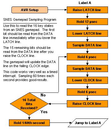
The transfer process only requires 3 I/O lines, so the ATMEL 2313 with it's 15 I/O pins will allow more than enough. The program has two registers that are used to hold the total 16 bits of the gamepad state: controller_h and controller_l. When a new bit arrives on the DATA line, I set or clear the carry flag based on whether the DATA was high or low; then I shift that carry flag into the controller_h register using the AVR's ROR (Rotate Right through carry) command. The ROR also moves the lowest bit of controller_h to the carry flag, so that I can pass it the controller_l register using a second ROR. If you include all of these functions into one short subroutine, it will greatly simplify the program. To sample the gamepad 60 times each second, the microcontroller needs to place a 1.728ms delay between keypad requests. At AVR clock speeds like 1, 4, or 10MHz, this amounts to long software delay, so you can use one of the AVR's timer-counter interrupts to repeat the code at 60Hz. The ATMEL data sheet describes how to set up the timer and it's prescaler register for whatever delay you want. There is also a very helpful program called AVR calc that can simplify the process by performing some of the timing calculations for you. I/O SettingsThat's pretty much all there is to sampling. Sometimes though, if your I/O lines have a very strong pull-resistor (placed internally within the chip, or externally by yourself), you may experience problems getting the correct data values. If you use pull-up resistors, it would be a good idea to keep their values between 50Kohms and 300Kohms. |
| Data |
SummarySince bit timing is the main pitfall with this kind of project, I think the main idea to keep in mind here is the fact that the SNES is essentially a 16-bit shift register. After that, the timing and troubleshooting becomes a lot more intuitive. In general, if you're in search of a gaming or machine-control keypad, I would actually recommend the Playstation Gamepad Interpreter because of its joystick functions. But, if you're looking for a fast and simple keypad, or you're just as nostalgic as I am, this is the gamepad for you. |
| Reference |
| Gamesx Article. SNES, NES, and Famicon Controller Data |