Playstation Controller Interpreter [E-22] | ||||||||
| <<< Home | Disclaimer | Glossary | Strategy | Hardware Theory | Software Theory | Data | Questions | Links >>> |
|---|---|---|---|---|---|---|---|---|
| Introduction: If you are in search of information or a pinout to the PSX controller, this guide is the place for you! | ||||||||
| Abstract | <<< Back |
|
This Playstation Controller Interpreter project can demonstrate how to read key and joystick data from a gamepad using only an embedded microntroller and a few discrete parts. Using a combination of hardware and low-level software, the treatise below will show how to test and detect the controller, establish a bit rate, and maintain the full-duplex connection needed for key sampling. This project was developed and tested for the ATMEL AVR 2313 microcontroller, however it may be ported to other platforms. |
| Disclaimer | ||||||
|
ALL INFORMATION WITHIN THIS DOCUMENT IS PROVIDED "AS IS" AND WITHOUT ANY EXPRESS OR IMPLIED WARRANTIES, INCLUDING, WITHOUT LIMITATION, THE IMPLIED WARRANTIES OF MERCHANTIBILITY AND FITNESS FOR A PARTICULAR PURPOSE. I DO NOT GUARANTEE ANY INFORMATION IN THIS DOCUMENT IS ACCURATE, AND IT SHOULD BE USED FOR ABSTRACT EDUCATIONAL PURPOSES ONLY. THIS SOFTWARE AND DOCUMENTATION IS FREE OF CHARGE. COPYRIGHT (C) 2005 BY BRADY MAYES. ALL RIGHTS RESERVED. REDISTRIBUTION AND USE IN SOURCE AND BINARY FORMS, WITH OR WITHOUT MODIFICATION, ARE PERMITTED PROVIDED THAT THE FOLLOWING CONDITIONS ARE MET: 1. REDISTRIBUTIONS OF SOURCE CODE MUST RETAIN THE ABOVE COPYRIGHT NOTICE, THIS LIST OF CONDITIONS AND THE FOLLOWING DISCLAIMER. 2. REDISTRIBUTIONS IN BINARY FORM MUST REPRODUCE THE ABOVE COPYRIGHT NOTICE, THIS LIST OF CONDITIONS AND THE FOLLOWING DISCLAIMER IN THE DOCUMENTATION AND/OR OTHER MATERIALS PROVIDED WITH THE DISTRIBUTION. 3. ALL ADVERTISING MATERIALS MENTIONING FEATURES OR USE OF THIS SOFTWARE MUST DISPLAY THE FOLLOWING ACKNOWLEDGEMENT: THIS PRODUCT INCLUDES SOFTWARE DEVELOPED BY B.MAYES AND ITS CONTRIBUTORS. THIS SOFTWARE IS PROVIDED BY B.MAYES AND CONTRIBUTORS ``AS IS'' AND ANY EXPRESS OR IMPLIED WARRANTIES, INCLUDING, BUT NOT LIMITED TO, THE IMPLIED WARRANTIES OF MERCHANTABILITY AND FITNESS FOR A PARTICULAR PURPOSE ARE DISCLAIMED. IN NO EVENT SHALL B.MAYES OR CONTRIBUTORS BE LIABLE FOR ANY DIRECT, INDIRECT, INCIDENTAL, SPECIAL, EXEMPLARY, OR CONSEQUENTIAL DAMAGES (INCLUDING, BUT NOT LIMITED TO, PROCUREMENT OF SUBSTITUTE GOODS OR SERVICES; LOSS OF USE, DATA, OR PROFITS; OR BUSINESS INTERRUPTION) HOWEVER CAUSED AND ON ANY THEORY OF LIABILITY, WHETHER IN CONTRACT, STRICT LIABILITY, OR TORT (INCLUDING NEGLIGENCE OR OTHERWISE) ARISING IN ANY WAY OUT OF THE USE OF THIS SOFTWARE, EVEN IF ADVISED OF THE POSSIBILITY OF SUCH DAMAGE. THIS FILE IS DISTRIBUTED IN THE HOPE THAT IT WILL BE USEFUL, BUT WITHOUT ANY WARRANTY; WITHOUT EVEN THE IMPLIED WARRANTY OF MERCHANTABILITY OR FITNESS FOR A PARTICULAR PURPOSE.
|
| Glossary |
|
PSX - There is some disagreement over what the meaning of the "X" here is, but this unmistakably refers to the first Playstation game system and no others, as the "X" might imply. It also goes by the name "PSOne" or "PS-1." Keypad - This is the game controller itself. Throughout this page, I will also refer to it sometimes as "the controller." It contains a microcomputer for communications. Sample Rate - By this, I mean the number of times the keypad is polled each second. The gaming industry seems to use a 60-sample-per-second standard in most platforms when one keypad is in use. High sample rates give more responsiveness, but is bad for multi-tasking and power consumption. Bit Rate - This is the clock rate used to communicate with the keypad. So far I've been able to achieve a top rate of around 24,000bps with the Playstation controller. Faster rates may be possible after more experimentation. NOP - No Operation. This is a program instruction that causes the processor to pause for exactly one clock cycle. Since this pause is small and predictable, it's useful for slowing or controlling the flow of a program or controlling your bit rate. Key Ghosting - Faulty key data. Ghosting is a very nasty problem that tricks your controller into thinking certain keys are active when they aren't really active at. It was a lot of causes in keypad designs (pressing too many keys, data bus impedance, using the wrong bit rate, etc.) Ghosting was a major problem in the first E-22 version. Key Masking - This is basically the opposite of ghosting. Masking is an unwanted phenomena to prevents certain keys from being read, even when they're active. It some of the same causes as ghosting, and the two sometimes go hand-and-hand. Interrupt - An interrupt is a segment of code that can be triggered by some special condition. The PSX Interpreter will use a precision timer interrupt, which runs over a hundred times each second. Once an interrupt is complete, the processor will return to the main program. Floating Pin - An input pin is said to be floating if it is not connected to anything. Floating pins may report random logic states unless pull-up or pull-down resistors are applied. Bypass Capacitor - A capacitor meant to absorb electrical spikes by providing an easy path to ground. A bypass usually has one pin tied to ground and the other pin attached to some supply lead. In this non-precision application any capacitor type can be used, as long as it fall within a reasonable range of value. Pull-Up Resistor - These go hand-and-hand with Open-Collect Outputs. Pull-ups allow these outputs to produce both logic highs and lows instead of just lows. To pull an output up, simply attach it to the supply voltage through a high-value resistor (this is your pull-up resistor). The resistance isn't critical, but most people use values above 1k to limit wasteful power absorption. The AVR has internal pull-ups on each IO pin, and they may be activated or deactivated by your software. Open-Collector Output - Open collector outputs are very important in electronics. In a nutshell, an OC output can bring itself low (logic 0). or it make itself float; it cannot product a high (logic 1). External pull-up resistors must be attached to the output in order for a high (logic 1) to be sent. |
| Design Strategy | ||||||||||||||||||||||||||||||||||||||||||||||||||||||||||||||||||||||||||||||||||||||||||||||||||||||||||||||||||||||||||||||||||||||||||||||||||||||||||||||||||||||||||||||||||||||||||||||||||||||||||||||||||||||||||||||||||||||||||||||||||||||||||||||||||||||||||||||||||||||||||||||||||||||||||||||||||||||||||||||||||||||||||||||||||||||||||||||||||||||||||||||||||||||||||||||||||||||||||||||||||||||||||||||||||||||||||||||||||||||||||||||||||||||||||||||||||||||||||||||||||||
Design ConceptBefore I begin, I would like to thank the writers over at http://www.gamesx.com/controldata/psxcont/psxcont.htm for providing thier excellent walkthrough on PSX formats. This guide uses the gamesx article for reference. Project Sub-initiativesController ResearchEven though PS2 controller data was sparse and PS3 data was obviously non-existent in 2004, I came across a good number of sites dedicated to controller pinouts and formats. The first thing that stuck out was the similarity to the older SNES and NES controllers, which --like the PSX-- send serial data in the standard TTL signal format. Since the AVR controller also uses the TTL format, its I/O pins can be "direct-linked" to the gamepad. Flow control is managed by synching the data to a clock pin. In summary, this controller had every indicator of being easy to interface to. With that said, we move on to the PSX pinout... Playstation Connector PinoutBelow is a generalized pinout of a Playstation controller. 
The diagram also applies to third-party and Playstation 2 (PS2) controllers, however the role of the two non-connected pins may be varied because of force feedback motors and other gizmos. As said above, every line uses TTL voltage levels. If you are using a low-voltage processor, you may need to step the controllers' output voltage down using a typical two-resistor voltage divider. Your circuit must also use a 100kOhm pull-up resistor on each input or else performance will be lowed and the max data rate will fall to about 1200bps or lower. Many microcontrollers (including the AVR series) have internal pull-up resistors that can be activated or deactivated by the software. There is a so-called "10th pin" on the bottom of the controller that resembles a small, square metal plate. This is a connection to the gamepad's shielding--a must for extended cables.
* The Black and Gray wires appear to be connected to each other. If the controllers wire is cut midway, tests will show a zero ohm resistance between these wires on the connector's end, and a 5K ohm resistance between these wires on the controllers end. ** Pin 8 is not connected to any wire or even the shielding. Single Byte FormatThe figure below shows a typical diagram of an 8-bit data frame. Keep in mind that this is a full-duplex transfer, which means that the Data and Command lines carry data at the same time--essentially making the cable a two-way street for data. Notice that the ACK line was activated by the PSX keypad without the clock. The ATT line is being left low because the transmission is not over. If this had been the final byte, we would have needed to rise the ATT line back after the last bit was sent.  [ Click for print version ] 1-byte transfers aren't terribly useful with the gamepad. A typical transfer will be done in 5 to 9-byte burst, performed about 60 times a second. To make a full data frame, follow the behavior of the above figure, and separate each byte by whatever time it takes for the ACK to arrive. Generally, this means bytes are separated by 60us. The only difference is that on the final byte, the ATT line must be set high (by you) after the final bit is transferred. Also, I reiterate that the gamepad will not acknowledge you on the final byte. The standard frame format for each of the gamepads is shown in the tables below: Controller ResearchAs of mid 2005, the Sony family of controllers comprises four keypad varieties, and one mouse to research. Each model is indicated by an 8-bit designator which may be retrieved by you during the initialization process. Here are the known controllers by ID number: Digital = 0x41 When the Playstation wants to initiate a conversation with the keypad, it will send 0x01 "Startup." In the next byte, the Playstation will send "0x42," which means "Request for data." At the same time, the keypad will send its model number in response to the "start up" command it got in the first byte. Next, the controller sends "0x5A" "Sending Data" while the Playstation idles. Now the Playstation starts receiving the key information. As you can see in the tables below, each key has a single assigned bit. If that key is pressed, the corresponding bit will be changed to "0." If one key appears to affect 2 or more bits, you are experiencing Ghosting. Ghosting will be covered later. Analog devices will send several 8-bit numbers that indicate their position or pressure (I'm told the NegCon uses pressure-sensitive keys and steering). Once again, all bytes should be followed by an "ACK" signal from the controller, except the last byte. Digital Controller
Analog Controllers
| ||||||||||||||||||||||||||||||||||||||||||||||||||||||||||||||||||||||||||||||||||||||||||||||||||||||||||||||||||||||||||||||||||||||||||||||||||||||||||||||||||||||||||||||||||||||||||||||||||||||||||||||||||||||||||||||||||||||||||||||||||||||||||||||||||||||||||||||||||||||||||||||||||||||||||||||||||||||||||||||||||||||||||||||||||||||||||||||||||||||||||||||||||||||||||||||||||||||||||||||||||||||||||||||||||||||||||||||||||||||||||||||||||||||||||||||||||||||||||||||||||||
| Hardware Theory | ||||||||||||||||||||||||||||||||||||||||||||||||||||||
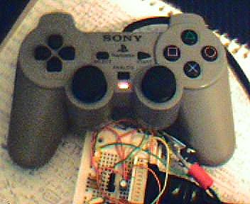
Electrical DesignHere is the test circuit that the control code was designed around. This system will show what buttons are being pressed by changing the pattern of lights shown in the bar graph display. To be more specific, I had my test program read the first byte of key data from the controller. As you press each key, the red bar display will turn off one LED. So for example, when I pressed the "left" button on my Analog (Red Mode) controller, I would see the uppermost LED turn off. The same concept worked the analog joysticks too, except the LEDs will display the binary value for each joystick position.
[ Click for larger image ] Schematic CommentsOnce again, this is a highly simplified (but not over-simplified) strategy for an interface. Unlike classic game joysticks, the key and joystick data has been processed internally by the gamepad's own digital-to-analog systems, so there is little left for us to do other than request the data. Cable shield grounding will be beneficial in high-RF noise environments. For instructions on the ground connection, see the theory section ["Playstation Connector Pinout"] above. Bill of Materials
Part RequirementsMicrocontrollerAbove all, the microcontroller or processor must be able to source up to 20mA (sustained) on all of its output leads. Exceeding this current is liable to cause permanent damage, which is why the 250-Ohm resistors are used as current-limiters on each of the "B" ports [see schematic above]. If processor cannot support such a high current, increase the value of the resistors using Ohm's Law (Resistance=Voltage/Current). If you have the 10MHz or newer 20MHz variants of the AVR2313 controller, you will be able to apply a faster clock crystal, but keep in mind the code listed above will not compensate for the speed change. This may cause communication problems, so adjust the code first. This schematic also assumes the microcontroller has built-in pull-up resistors placed on the DATA and ACK input leads. Not all processors have this function. If your inputs lack an internal pull-up, you will have to create one by connecting the line to the + Supply through a 100kOhm resistor. Voltage RegulatorOther than software, the aspect most likely to cause problems for the system is supply noise. Thankfully, with a battery-operated system like the E22 experimental circuit, this is unlikely to noise. But precautions are always welcomed. First and foremost, you must make sure the voltage applied to the regulator is high enough to overcome the regulator's natural dropout voltage. This dropout is usually on the order of 1-3volts for a "standard-issue" regulator like a LM7805, so expect to apply an input voltage higher than 7.5 or 8 Volts. My LM7805 regulator has 7.5V listed as the preferred minimum, so a standard 9-Volt alkaline cell worked just fine. A large electrolytic capacitor on the output lead will ensure short-term stability. EngineeringSo, you're finally ready to begin building your interface. If you're like me you're probably planning on using a pre-owned gamepad. There is a bit of a risk here, because you may not have a means of determining how well the keypad works--or if it still works at all. There are a number of ways you can test a controller using a minimum of equipment: Use a Real Playstation If it seems too obvious, don't be phased: you can save a lot of anguish with these simple shortcuts. Start by noting the performance of each key and check for stuck buttons or any other problems that may suggest damage. After making a casual record of its performance, move on to the next step. Simple Analog Light Test All but the earliest of PSX gamepads will allow you the option to switch between digital-only and joystick ("analog") modes. If you want to test this controller, simply apply a +5 voltage between the controller's Vcc and GND pins. Now press the "analog" button. If the light does not activate, you may have your pins reversed or the controller may be seriously damaged. If the light works, you can move on to the next test... Simple Clock and ACK Test To test the keypad's microcomputer, you need a logic probe with a pulse-detection option. Connect the Vcc and GND pins but don't power up yet. First, connect the clock pin to a 2400Hz square wave generator or microcontroller (555 timers work well, too). Next, connect the ATT pin directly to ground. Power up the keypad, turn on the oscillator and touch the logic probe to the keypad's ACK pin. The probes "pulse" lamp should begin blinking rapidly. This shows that the keypad's microcomputer is still working and is acknowledging the data line. If the probe's lights are not alternating at all, recheck your connections once more. If the problem still persists, its probably time to return that controller and get your money back. | ||||||||||||||||||||||||||||||||||||||||||||||||||||||
| Software Theory | ||||||||||||||||||||
Software Layout
The above software may be used to display the controller's key states through several output LEDs. The program is hardware-compatible with the schematic featured below. This software was tested and uploaded using ATMEL AVR Studio 4.
The key-reading interrupt used in the E-22 system was based on the flowchart below. Interrupts however are only one option, you can simplify the process slightly by avoiding interrupts altogether. This section will cover the simplified method first, following by the interrupt approach--which will let the program read the gamepad outside of the main program loop. 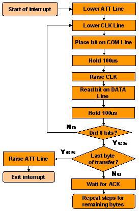
On-demand Approach: One-Shot ReadThis method is generally useful where aperiodic sampling is acceptable. The advantage is that it requires fewer processor resources (like registers or interrupts) than the interrupt-driven strategy. Unfortunantely this simpler method forfeits some of the hidden advantages of periodic sampling, but with rapid sampling rates, you can still reconstruct the user's keystrokes well enough to fit most applications. The first step I took was to pre-initialize the I/O ports. Don't neglect to pre-set the outputs of CLK, ATT, and COMM lines or else your PSone keypad will probably go ballistic. Using my descriptions of the pin assignments, you will have to clock data in and out of the controller at a periodic interval. I was not able to determine how precise the clocking measure had to be, so I kept the clock running at a constant 50% duty cycle. The interval and duty cycle may be adjusted by inserting "nop" instructions between clock toggles. In practical terms, on-demand key reads are not very useful because the user's keystrokes will be arbitrary. Instead, you will probably want to have free-running key checks that are conducted at regular intervals. For this reason, most of this treatise will cover the interrupt-based approach. Interrupt-based ApproachMost of the time, you might wish to have the processor poll the PSOne controller constantly--without having to "call" an on-demand key-reader routine. If your processor supports timer/counter-triggered interrupts, you may be able to accomplish this. The AVR version ran off a 4.00MHz clock source with a divide-by-64 prescale, giving the timer a 16us interval. In other words, the interrupt rate was be controlled by this property: Polling each 16us is much too rapid, so to increase the interval further , I used a 16-bit timer/counter register (TCCR1) as a time keeper. Next, I loaded a value of 0x0411, or "1041" into the timer-compare register (OCR1A). This allows E-22 to activate it's timer-compare-match interrupt every 16.672ms (16us * (1041+1)). These timers and counters are explained in more detail in the source code. The main thing to keep in mind is that you probably do not want to sample much faster than 60 times a second. Referring back to the flowchart above, notice that the entire communication sequence took place in one long interrupt cycle. This method has some inherent advantages and disadvantages. The main advantage is that the code is much easier to read and debug. It also prevents the main key-interpreting loops from reading incomplete key frames. The disadvantage is the processor "downtime" due to the long 100us waiting periods between bytes in which nothing happens. You could eliminate some of the downtime by either sampling at lower rates--below 30 samples per second, or --with some imagination-- re-write your interrupt to sample 1 bit at a time. |
| Data |
Project's Development ReviewWhen I made my first versions of the project, I accidentally deactivated the AVR's internal pull-ups instead of activating them. As a result, I witnessed serious key ghosting and my bitrates were restricted to less than 2400bps. I highly recommend the use of a 100KOhm resistor as a voltage pull-up on each input. Place them on your DATA and ACK pins. No other problems were apparant. Project's Operation ReviewThe system operates very well, with no known bugs or crashes to report. Since the E-22 project has no permanent enclosure or circuitboard at this time, I have not submitted it to the standard 1000-hour test applied to the other E-series programs. The upcoming E-27 security project may change this. In any case, both the hardware and software featured above are highly reliable. SummaryIn closing, this was a very successful project, due mostly in part to the thorough information on this gamepad model. Sony's use of TTL makes device and PC interfacing a lot easier than most would first think. As of now, I have operated the E-22 system at clock rates exceeding 192,000bps will no negative consequence. For the time being, this is a very adequate frequency so I have not pursued a higher rate. In the future, I plan to use this software to try and document the format for the newer PS2 "Dual Shock" gamepads, and possibly the upcoming PS3 if it's controller has not been radically changed. |
| Questions |
|
Here are some questions I've seen regarding similar projects. Q: How can I interface this to a PC? Q: Hey, you don't have the controller I wanted! Q: So what about the mouse? Q: Will this work with Playstation 2 or PS3? Q: What about 3rd-Party controllers? Q: How can I use multiple controllers? |