Infrared Transmitter | ||||||
| <<< Home | Disclaimer | Hardware Theory | Software Theory | Data | Reference | Links >>> |
| Abstract | <<< Back |
|
The AVR Basic Infrared Transmitter is a sister project for the Basic Infrared Reciever. The emphasis here is on "basic" because the simplest version can be built using only 10 discrete components and a typical AVR microcontroller. Taken together, these two projects will allow your projects to be remotely operated for distances averaging as far as 10 meters. |
| Disclaimer |
|
ALL INFORMATION WITHIN THIS DOCUMENT IS PROVIDED "AS IS" AND WITHOUT ANY EXPRESS OR IMPLIED WARRANTIES, INCLUDING, WITHOUT LIMITATION, THE IMPLIED WARRANTIES OF MERCHANTIBILITY AND FITNESS FOR A PARTICULAR PURPOSE. I DO NOT GUARANTEE ANY INFORMATION IN THIS DOCUMENT IS ACCURATE, AND IT SHOULD BE USED FOR ABSTRACT EDUCATIONAL PURPOSES ONLY. THIS SOFTWARE AND DOCUMENTATION IS FREE OF CHARGE. COPYRIGHT (C) 2005 BY BRADY MAYES. ALL RIGHTS RESERVED. REDISTRIBUTION AND USE IN SOURCE AND BINARY FORMS, WITH OR WITHOUT MODIFICATION, ARE PERMITTED PROVIDED THAT THE FOLLOWING CONDITIONS ARE MET: 1. REDISTRIBUTIONS OF SOURCE CODE MUST RETAIN THE ABOVE COPYRIGHT NOTICE, THIS LIST OF CONDITIONS AND THE FOLLOWING DISCLAIMER. 2. REDISTRIBUTIONS IN BINARY FORM MUST REPRODUCE THE ABOVE COPYRIGHT NOTICE, THIS LIST OF CONDITIONS AND THE FOLLOWING DISCLAIMER IN THE DOCUMENTATION AND/OR OTHER MATERIALS PROVIDED WITH THE DISTRIBUTION. 3. ALL ADVERTISING MATERIALS MENTIONING FEATURES OR USE OF THIS SOFTWARE MUST DISPLAY THE FOLLOWING ACKNOWLEDGEMENT: THIS PRODUCT INCLUDES SOFTWARE DEVELOPED BY B.MAYES AND ITS CONTRIBUTORS. THIS SOFTWARE IS PROVIDED BY B.MAYES AND CONTRIBUTORS ``AS IS'' AND ANY EXPRESS OR IMPLIED WARRANTIES, INCLUDING, BUT NOT LIMITED TO, THE IMPLIED WARRANTIES OF MERCHANTABILITY AND FITNESS FOR A PARTICULAR PURPOSE ARE DISCLAIMED. IN NO EVENT SHALL B.MAYES OR CONTRIBUTORS BE LIABLE FOR ANY DIRECT, INDIRECT, INCIDENTAL, SPECIAL, EXEMPLARY, OR CONSEQUENTIAL DAMAGES (INCLUDING, BUT NOT LIMITED TO, PROCUREMENT OF SUBSTITUTE GOODS OR SERVICES; LOSS OF USE, DATA, OR PROFITS; OR BUSINESS INTERRUPTION) HOWEVER CAUSED AND ON ANY THEORY OF LIABILITY, WHETHER IN CONTRACT, STRICT LIABILITY, OR TORT (INCLUDING NEGLIGENCE OR OTHERWISE) ARISING IN ANY WAY OUT OF THE USE OF THIS SOFTWARE, EVEN IF ADVISED OF THE POSSIBILITY OF SUCH DAMAGE. THIS FILE IS DISTRIBUTED IN THE HOPE THAT IT WILL BE USEFUL, BUT WITHOUT ANY WARRANTY; WITHOUT EVEN THE IMPLIED WARRANTY OF MERCHANTABILITY OR FITNESS FOR A PARTICULAR PURPOSE. |
| Hardware Theory | ||||||||||||||||||||||||||||||||||||||||||||||||||||||||||||||||||
Electrical Design
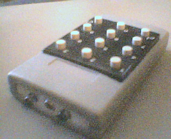
Schematic CommentsThis IR circuit uses a 4x4 sized keypad for the user. The 74C922 chip can encode these types of keystrokes into a 4-bit number. Use the keypad encoder sub-circuit to read key data from the 4x4 matrix. Bill of Materials
Part RequirementsMicrocontroller FrequencyThe operating frequency is critical since it directly controls the bitrate. The AVR program on this page was designed for a 4.00MHz clock. If you need a different bitrate, please view the software section below for details on how to rewrite the program for other clock rates. Microcontroller I/OBe aware of how much current will be drawn by your infrared emitter, especially when using "high-output" or "high-brightness" diodes. Often, these diodes require 100mA for peak emission, which is much greater than the 20mA or 30mA garden-variety controllers are designed to take. Infrared DiodeNot all infrared emitters are created equal. Like visible LEDs, each has a distinct wavelength (measured in nanometers), which would corespond to a color if we could view it. Before choosing an emitter, know that your receiver will have an "infrared passband" that will filter out any wavelengths that don't fall within that range. My receiver had an advertised passband of 940nm +/- 50nm--or 890nm to 990nm. The emitters I purchased were rated 915nm. Not an ideal match, but well within the limits. On the market, I've seen diodes with wavelengths as long as 1550nm, so beware if purchasing an unknown diode. EngineeringThanks to the software-generated carrier, no signal mixing is required and the engineering burden is mostly shifted onto the software aspect. In general the system's simplicity makes it possible to build a highly robust transmitter out of nearly any grade of electronic component. |
| Software Theory | |||||||||||||||
Device Software
Software DesignFor a description of the RC5 remote control protocol, and the a description of the protocol I used in this device, view the Basic Infrared Receiver Software Design section.
Since we are applying the RC5 protocol, we need the data to modulate a 36kHz carrier signal. Normally this carrier would be generated by a seperate oscillator and combined with the output of the AVR. But to minimise circuit size, we will generate the carrier within the AVR program itself. My AVR is operating with a 4.00MHz clock frequency. If we invert 4x10^6, we can see that the clock period (or "T state") is 0.25us. Most AVR instructions take only 1 or 2 clock periods to complete. By looking at the data sheet, I could tell exactly how long each instruction lasts and use that to toggle the output pins precisely at 36kHz. Doing the math, take the inverse of 36,000Hz--which yeilds 27.8us. To express this in terms of T-states, multiply the clock frequency by the delay we want: ...So at 4MHz, there needs to be approximately 111 T-states between each carrier wave period. So for example: we could raise the line for 55 T-states, and lower it for 56 T-states. Once again, at 4.00MHz, one T-state spans 0.25us. Other ways to Generate the CarrierBy adding additional components to the circuit, you can use an oscillator set to produce 36kHz, and eliminate the need to have the software generate the carrier. This would speed up developement time and free up critical processor time for other tasks. Since the square wave carrier is created on an on/off basis, a 555 timer or similar signal source could be used. The AVR allows you to use such an external signal source and an interrupt trigger, so this can free up an additional amount of processing time. |
| Data |
Operational ReviewThe software-generate carrier operated at 37.037kHz rather than the nominal 36.0kHz due to software restrictions. Despite this, the IR output still visible to Phillips devices at ranges averaging 10 meters indoors. The max operating range with the IR receiver project was slightly farther under the same conditions, with the range being about 12 meters. A minimum operating range of 7 centimeters was also observed. SummaryIn summary, the system worked very well with Phillips equipment and the IR receiver project. However, for future reference, I would only suggest using an external carrier signal source over the software-generated carrier approach. This move would free up significant processing time and other resources (timers, registers) for the AVR. If the software-generated carrier is still required, I would suggest using an AVR hardware timer to control bit flow, as this would allow the AVR to carry out other tasks between bit transitions. |
| Reference |
|
RC5 Information Sources:
1. SB Projects. San Bergmans, Oisterwijk http://www.xs4all.nl/~sbp/knowledge/ir/rc5.htm 2. Davshomepage. De Vleeschauwer David http://users.pandora.be/davshomepage/rc5.htm3. Koninklijke Philips Electronics N.V. http://www.remotecontrol.philips.com/index.cfm?id=105. 2004-2005 |